


FOUR INPUT VIDEO MIXER
#video mixer
#radar system
#positive-polarity
#pulse combining
#signal processing
#NBS
#Navy Aeronautical
#electron tube
#1963
#marker pulses
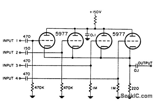
Description: This circuit is utilized for combining four distinct positive-polarity marker pulses in a radar system. The reference for this information is the "Handbook Preferred Circuits Navy Aeronautical Electronic Equipment," Volume 1, Electron Tube Circuits, published in 1963, page N4-1.
The circuit for combining four positive-polarity marker pulses is essential in radar systems to ensure accurate signal processing and synchronization. The design typically employs a series of resistors and capacitors to manage the timing and amplitude of the incoming pulses. Each marker pulse is generated by separate components, which may include oscillators or pulse generators, and is then fed into a summing circuit.
The summing circuit could utilize operational amplifiers (op-amps) configured in a summing amplifier arrangement. This configuration allows for the integration of multiple input signals while maintaining the integrity of the positive-polarity characteristics. The use of feedback resistors in the op-amp circuit ensures that the output pulse maintains the desired amplitude and shape, suitable for further processing stages in the radar system.
Additionally, the circuit may include filters to eliminate any unwanted noise or interference that could affect the clarity of the combined markers. Proper grounding and shielding techniques are also crucial in radar applications to prevent electromagnetic interference from degrading the performance of the marker pulses.
In summary, the circuit's design focuses on effectively combining multiple positive-polarity marker pulses while ensuring stability and fidelity of the signals within the radar system. This functionality is vital for the accurate operation and performance of radar equipment in various applications.Used for combining four different positive-polarity marker pulses in radar system. -NBS, "Handbook Preferred Circuits Navy Aeronautical Electronic Equipment, " Vol. 1, Electron Tube Circuits, 1963, p N4-1.
The circuit for combining four positive-polarity marker pulses is essential in radar systems to ensure accurate signal processing and synchronization. The design typically employs a series of resistors and capacitors to manage the timing and amplitude of the incoming pulses. Each marker pulse is generated by separate components, which may include oscillators or pulse generators, and is then fed into a summing circuit.
The summing circuit could utilize operational amplifiers (op-amps) configured in a summing amplifier arrangement. This configuration allows for the integration of multiple input signals while maintaining the integrity of the positive-polarity characteristics. The use of feedback resistors in the op-amp circuit ensures that the output pulse maintains the desired amplitude and shape, suitable for further processing stages in the radar system.
Additionally, the circuit may include filters to eliminate any unwanted noise or interference that could affect the clarity of the combined markers. Proper grounding and shielding techniques are also crucial in radar applications to prevent electromagnetic interference from degrading the performance of the marker pulses.
In summary, the circuit's design focuses on effectively combining multiple positive-polarity marker pulses while ensuring stability and fidelity of the signals within the radar system. This functionality is vital for the accurate operation and performance of radar equipment in various applications.Used for combining four different positive-polarity marker pulses in radar system. -NBS, "Handbook Preferred Circuits Navy Aeronautical Electronic Equipment, " Vol. 1, Electron Tube Circuits, 1963, p N4-1.

Interpolating Scanner Circuit
This design is for an interpolating scanner, a circuit featuring multiple signal inputs, a control voltage input, and a signal output. The output selectively transitions between inputs, smoothly fading from one to the next as the control voltage increases. A...

TRIPLE INPUT VIDEO MIXER
Each grid is biased to cutoff, allowing the mixer to accept only positive-polarity pulses with sufficient amplitude to overcome this bias. -NBS, "Handbook Preferred Circuits Navy Aeronautical Electronic Equipment," Vol. 1, Electron Tube Circuits, 1963, p N4-2.
In a typical mixer...

THREE INPUT VIDEO MIXER
Utilized in radar systems for the integration of any three of the following components: radar video, beacon, range markers, range strobe, and azimuth markers. -NBS, "Handbook Preferred Circuits Navy Aeronautical Electronic Equipment," Vol. 1, Electron Tube Circuits, 1963, p N4-1.
In...
HIGH PERFORMANCE VIDEO MIXER
This circuit combines horizontal synchronization (H sync), vertical synchronization (V sync), and the actual video signal. Transistor T2 is responsible for mixing the synchronization signals, while transistor T1 functions as an emitter-follower. Typical bandwidths for this circuit can reach up...