


HIGH PERFORMANCE VIDEO MIXER
#video mixer
#synch mixing
#emitter-follower
#high bandwidth
#25 MHz
#video processing
#signal mixing
#T1 transistor
#T2 transistor
#video synch
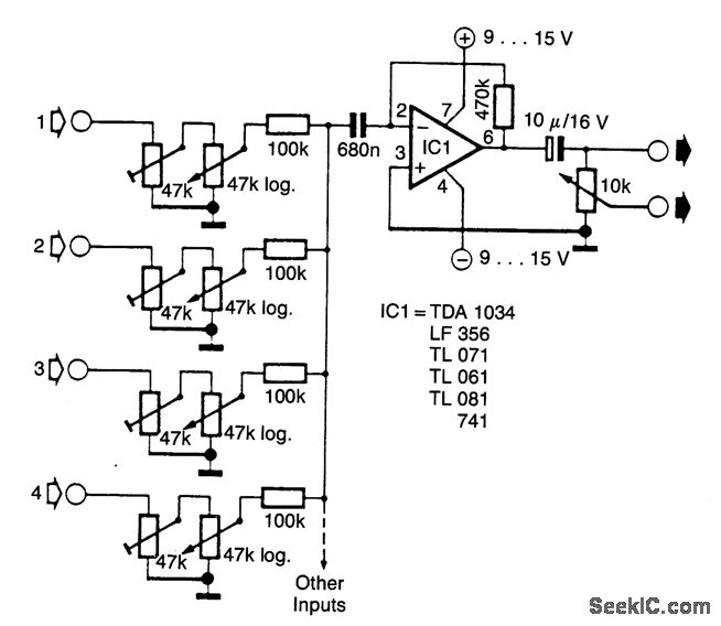
Description: This circuit combines horizontal synchronization (H sync), vertical synchronization (V sync), and the actual video signal. Transistor T2 is responsible for mixing the synchronization signals, while transistor T1 functions as an emitter-follower. Typical bandwidths for this circuit can reach up to 25 MHz.
The described circuit is a fundamental component in video processing, particularly in the context of analog video systems. The integration of H sync, V sync, and video signals is crucial for maintaining proper synchronization between the displayed image and the video source.
Transistor T2 plays a pivotal role in the mixing process, where it combines the synchronization signals to ensure that the timing of the video display aligns accurately with the incoming video data. This mixing is essential for preventing issues such as tearing or misalignment in the displayed image.
Transistor T1, acting as an emitter-follower, provides a high input impedance and low output impedance, which is beneficial for buffering the mixed signal. This configuration allows the circuit to drive subsequent stages without loading down the previous stage, thus preserving signal integrity. The emitter-follower configuration is advantageous in applications where signal isolation is necessary, and it helps to maintain the fidelity of the video signal.
The circuit's bandwidth capability of up to 25 MHz indicates its suitability for standard video resolutions, making it effective for various applications including television broadcasting and video conferencing systems. The design considerations for achieving this bandwidth include careful selection of components and layout to minimize parasitic capacitance and inductance, which can adversely affect performance.
Overall, this circuit exemplifies a critical aspect of video signal processing, where synchronization and signal integrity are paramount for delivering high-quality video output.This circuit mixes H synch. V synch. and actual video. T2 mixes the synch, while T1 serves as an emitter-follower. Bandwidths of up to 25 MHz are typical for this circuit.
The described circuit is a fundamental component in video processing, particularly in the context of analog video systems. The integration of H sync, V sync, and video signals is crucial for maintaining proper synchronization between the displayed image and the video source.
Transistor T2 plays a pivotal role in the mixing process, where it combines the synchronization signals to ensure that the timing of the video display aligns accurately with the incoming video data. This mixing is essential for preventing issues such as tearing or misalignment in the displayed image.
Transistor T1, acting as an emitter-follower, provides a high input impedance and low output impedance, which is beneficial for buffering the mixed signal. This configuration allows the circuit to drive subsequent stages without loading down the previous stage, thus preserving signal integrity. The emitter-follower configuration is advantageous in applications where signal isolation is necessary, and it helps to maintain the fidelity of the video signal.
The circuit's bandwidth capability of up to 25 MHz indicates its suitability for standard video resolutions, making it effective for various applications including television broadcasting and video conferencing systems. The design considerations for achieving this bandwidth include careful selection of components and layout to minimize parasitic capacitance and inductance, which can adversely affect performance.
Overall, this circuit exemplifies a critical aspect of video signal processing, where synchronization and signal integrity are paramount for delivering high-quality video output.This circuit mixes H synch. V synch. and actual video. T2 mixes the synch, while T1 serves as an emitter-follower. Bandwidths of up to 25 MHz are typical for this circuit.

Video Digitizer Project
This is the original Circuit Cellar ImageWise Transmitter that was initially used. The code was disassembled to capture two half-size images, allowing for the extraction of images from both the odd and even fields. Code was then written to subtract...

THREE INPUT VIDEO MIXER
Utilized in radar systems for the integration of any three of the following components: radar video, beacon, range markers, range strobe, and azimuth markers. -NBS, "Handbook Preferred Circuits Navy Aeronautical Electronic Equipment," Vol. 1, Electron Tube Circuits, 1963, p N4-1.
In...

ARCHITECTURES FOR VIDEO PROCESSING
The primary inquiry to address is the contemporary understanding of video processing. Until the late 1980s, two distinct realms existed: the analog television domain and the digital computing domain. All television processing, from the camera to the receiver, relied on...

TRIPLE INPUT VIDEO MIXER
Each grid is biased to cutoff, allowing the mixer to accept only positive-polarity pulses with sufficient amplitude to overcome this bias. -NBS, "Handbook Preferred Circuits Navy Aeronautical Electronic Equipment," Vol. 1, Electron Tube Circuits, 1963, p N4-2.
In a typical mixer...
Video Digitizer Project
This is the original Circuit Cellar ImageWise Transmitter that was initially used. The code was disassembled to capture two half-size images, allowing for the extraction of images from both the odd and even fields. Code was then written to subtract...

Single chip TV chroma luma processor
The CA3217E integrates all necessary circuit functions between the video detector and the RGB driver stages of a color television receiver. It decodes chroma signals to generate three distinct color signals, which are then combined with the luma to produce...

Triple Emitter-Follower as OPS for the Aikido
A hybrid amplifier is being developed, utilizing an Aikido configuration for the voltage amplification stage (VAS) and an emitter-follower variation for the output stage (OPS).
The hybrid amplifier design integrates two distinct amplification stages to achieve high performance and efficiency....
FOUR INPUT VIDEO MIXER
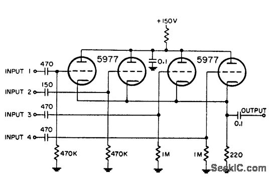
This circuit is utilized for combining four distinct positive-polarity marker pulses in a radar system. The reference for this information is the "Handbook Preferred Circuits Navy Aeronautical Electronic Equipment," Volume 1, Electron Tube Circuits, published in 1963, page N4-1.
The circuit...