


smartcard pc cable pinout.
#smartcard
#SIM card
#PC adapter
#ISO 7816
#D-SUB connector
#chip card
#GSM
#pay-TV
#reader/writer
#pinout

Description: Pinout of a smart card (SIM card) to PC adapter cable (SIM reader/writer) schematic and layout of a 6-pin SIM card special connector and a 9-pin D-SUB female connector used to connect computers to ISO 7816 compatible chip card systems (e.g., GSM mobile phones or pay-TV decoding systems).
The schematic for the SIM card to PC adapter cable is essential for establishing communication between a computer and ISO 7816 compliant smart cards, which are widely used in applications such as mobile telephony and digital television services. The layout involves two primary connectors: a 6-pin connector for the SIM card and a 9-pin D-SUB female connector that interfaces with the computer.
The 6-pin SIM card connector typically includes the following pin assignments:
1. **VCC** - The power supply pin that provides the necessary voltage to the SIM card.
2. **GND** - The ground connection, which serves as the reference point for the power supply.
3. **I/O** - The input/output pin used for data communication between the SIM card and the host device.
4. **RST** - The reset pin that initializes the SIM card.
5. **CLK** - The clock signal pin that synchronizes data transmission.
6. **VPP** - The programming voltage pin, which is used for specific operations during card programming.
The 9-pin D-SUB female connector connects to the computer and typically follows the standard RS-232 pinout configuration. The relevant pins include:
1. **Pin 1 (DCD)** - Data Carrier Detect.
2. **Pin 2 (RXD)** - Receive Data, which receives data from the SIM card.
3. **Pin 3 (TXD)** - Transmit Data, which sends data to the SIM card.
4. **Pin 4 (DTR)** - Data Terminal Ready, indicating that the device is ready to communicate.
5. **Pin 5 (GND)** - Ground connection for signal reference.
6. **Pin 6 (DSR)** - Data Set Ready, indicating that the SIM card is ready to communicate.
7. **Pin 7 (RTS)** - Request to Send, used to control data flow.
8. **Pin 8 (CTS)** - Clear to Send, indicating that the device can send data.
9. **Pin 9 (RI)** - Ring Indicator, used for signaling.
The connection between the SIM card and the computer allows for the reading and writing of data to the SIM card, enabling functionalities such as contact management, SMS operations, and application management. This schematic is crucial for developers and engineers working with smart card technology, ensuring proper interfacing and communication protocols are adhered to for reliable operation. Proper attention to the pin configuration and electrical characteristics is essential to prevent damage to the components and ensure optimal performance.Pinout of Smart card (Sim card) to PC adapter cable (sim reader/writer) schematic and layout of 6 pin Simcard special connector and 9 pin D-SUB female connectorused to to connect computers to ISO 7816 compatible chip card systems (e.g. GSM mobile phones or pay-TV decoding systems)..
The schematic for the SIM card to PC adapter cable is essential for establishing communication between a computer and ISO 7816 compliant smart cards, which are widely used in applications such as mobile telephony and digital television services. The layout involves two primary connectors: a 6-pin connector for the SIM card and a 9-pin D-SUB female connector that interfaces with the computer.
The 6-pin SIM card connector typically includes the following pin assignments:
1. **VCC** - The power supply pin that provides the necessary voltage to the SIM card.
2. **GND** - The ground connection, which serves as the reference point for the power supply.
3. **I/O** - The input/output pin used for data communication between the SIM card and the host device.
4. **RST** - The reset pin that initializes the SIM card.
5. **CLK** - The clock signal pin that synchronizes data transmission.
6. **VPP** - The programming voltage pin, which is used for specific operations during card programming.
The 9-pin D-SUB female connector connects to the computer and typically follows the standard RS-232 pinout configuration. The relevant pins include:
1. **Pin 1 (DCD)** - Data Carrier Detect.
2. **Pin 2 (RXD)** - Receive Data, which receives data from the SIM card.
3. **Pin 3 (TXD)** - Transmit Data, which sends data to the SIM card.
4. **Pin 4 (DTR)** - Data Terminal Ready, indicating that the device is ready to communicate.
5. **Pin 5 (GND)** - Ground connection for signal reference.
6. **Pin 6 (DSR)** - Data Set Ready, indicating that the SIM card is ready to communicate.
7. **Pin 7 (RTS)** - Request to Send, used to control data flow.
8. **Pin 8 (CTS)** - Clear to Send, indicating that the device can send data.
9. **Pin 9 (RI)** - Ring Indicator, used for signaling.
The connection between the SIM card and the computer allows for the reading and writing of data to the SIM card, enabling functionalities such as contact management, SMS operations, and application management. This schematic is crucial for developers and engineers working with smart card technology, ensuring proper interfacing and communication protocols are adhered to for reliable operation. Proper attention to the pin configuration and electrical characteristics is essential to prevent damage to the components and ensure optimal performance.Pinout of Smart card (Sim card) to PC adapter cable (sim reader/writer) schematic and layout of 6 pin Simcard special connector and 9 pin D-SUB female connectorused to to connect computers to ISO 7816 compatible chip card systems (e.g. GSM mobile phones or pay-TV decoding systems)..
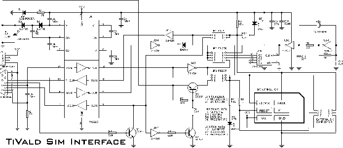
Sim card to PC adapter cable
The electronic adapter derives its power supply from the VCC line of the smartcard reader device, or alternatively, an external 5 V supply can be utilized. The RST line of the card slot is connected to one of the TTL...

Smartcard controlled Lock with Relay
This design uses a smart card to enable a relay. A Nutchip recognizes its mating smart card among thousand similar ones, because you choose the code to be programmed in the card's memory. No specialized knowledge is necessary, as we...

Small Breakout for SIM900 GSM Module
The printed circuit board features a 10-pin by 2-pin strip used for connection with the circuit board of the remote control device. Pin 1 (ON/OFF) is utilized by a microcontroller to control the power state of the GSM module. The...

GSM Based Voting Machine System ECE Project Report
This project involves a GSM-based voting machine system that utilizes AT commands to send SMS through a microcontroller. It operates in two modes: Normal mode, where an authorized individual from a local area can cast their vote, and Security mode,...

Simple PC smartcard reader
This simple PC Smartcard reader was shown in Electronics Design magazine February 17, 1997 issue on page 172 in the ideas for design section. The circuit is designed by Jose Carlos Cossio and is based on simple smartcard reader design...

gsm gps based vehicle theft control
This project focuses on the design and development of a theft control system for automobiles, aimed at preventing and controlling vehicle theft. The system utilizes an embedded design based on GSM and GPS technology. It is installed within the vehicle...

Programmable Control For Home Safety via GSM Remote
How to turn on equipment by sending SMS `1111` to switch it ON and switch off the equipment by sending SMS `0000`. The GSM switch will receive instructions for either load 1 (L1), load 2 (L2), load 3 (L3), or...

GSM Based Home Automation Project Report
This project focuses on GSM-Based Home Automation and has been submitted as part of the requirements for a Bachelor of Technology degree in Electronics and Communication Engineering. The objective of the project is to create a system that utilizes mobile...

GSM Voice Dialer with Automation Control
Connected to a burglar alarm or fire alarm, this device facilitates phone calls that play voice messages. It is controlled via DTMF actuators, allowing for immediate operation. In recent years, several telecontrols based on the SIM900 GSM module have been...