


123 Game - All MCU-free circuit
#game circuit
#logic gates
#no microcontroller
#electronic game
#human vs machine
#digital circuit
#turn-based game
#educational
#fun project
#simple circuit

Description: This electronic game pits a human player against the machine. The opponents use a common game token and take turns moving along a path by one, two, or three steps, with the winner being the first to reach the goal exactly. Remarkably, this simple version of the 123 game can be constructed without a microcontroller, making it nearly unbeatable.
The electronic game described operates on a straightforward principle involving turn-based movement along a defined path. The path is segmented into discrete steps, allowing players to move their game token one, two, or three steps forward during their turn. The objective of the game is to be the first player to land exactly on the designated goal position. This straightforward mechanic introduces a strategic element, as players must consider their moves carefully to either reach the goal or block the opponent's path.
The absence of a microcontroller in the design simplifies the circuit, relying instead on basic electronic components such as switches, resistors, and possibly a simple LED indicator to denote the current player's turn. The game can be enhanced with a simple counter or a series of toggle switches to track the position of each player's token along the path.
A potential schematic for this game could include two push-button switches for player input, where each button corresponds to a player’s turn. Each switch is connected to a series of resistors and a logic circuit that determines the allowed movement options (one, two, or three steps). The game board can be represented with a series of LED lights or a segmented display to visualize the current positions of the tokens. An additional feature may include a reset button to restart the game after a player wins.
The design emphasizes user interaction and strategic gameplay, making it accessible for players of all ages. The simplicity of the circuit ensures that it can be built with basic electronic skills, allowing for educational opportunities in electronics and game design.This electronic game pits a human player against the ˜machine. The opponents use a common ˜game token and take turns moving along a path by one, two or three steps, and the winner is the first one to reach the goal exactly. Incredibly enough, this simple version of the ˜123 game can be built without a microcontroller, and it s almost impossible to beat..
The electronic game described operates on a straightforward principle involving turn-based movement along a defined path. The path is segmented into discrete steps, allowing players to move their game token one, two, or three steps forward during their turn. The objective of the game is to be the first player to land exactly on the designated goal position. This straightforward mechanic introduces a strategic element, as players must consider their moves carefully to either reach the goal or block the opponent's path.
The absence of a microcontroller in the design simplifies the circuit, relying instead on basic electronic components such as switches, resistors, and possibly a simple LED indicator to denote the current player's turn. The game can be enhanced with a simple counter or a series of toggle switches to track the position of each player's token along the path.
A potential schematic for this game could include two push-button switches for player input, where each button corresponds to a player’s turn. Each switch is connected to a series of resistors and a logic circuit that determines the allowed movement options (one, two, or three steps). The game board can be represented with a series of LED lights or a segmented display to visualize the current positions of the tokens. An additional feature may include a reset button to restart the game after a player wins.
The design emphasizes user interaction and strategic gameplay, making it accessible for players of all ages. The simplicity of the circuit ensures that it can be built with basic electronic skills, allowing for educational opportunities in electronics and game design.This electronic game pits a human player against the ˜machine. The opponents use a common ˜game token and take turns moving along a path by one, two or three steps, and the winner is the first one to reach the goal exactly. Incredibly enough, this simple version of the ˜123 game can be built without a microcontroller, and it s almost impossible to beat..

Electronics Cricket
The electronics cricket game circuit presented on this website is a straightforward and easy-to-build circuit diagram for an electronics cricket project, as well as various other game projects.
The electronics cricket game circuit typically consists of several key components that work...

Electronic potentiometer circuit composed of digital circuits
Figure 4-14 illustrates a digital integrated circuit featuring 16 preset potentiometers for Siniperca electronic circuits. The circuit comprises three main components: an input controller, a presettable counter, an analog electronic switch, and a resistor network. It includes a push-button switch...

Simple Game Circuit
This is a simple game circuit designed for multiplayer enjoyment. The objective is to score one hundred points within a limited timeframe. To restart the game, the S1 button switch must be pressed. It is important to ensure that the...

Pot shot
This circuit is designed for a shooting gallery-style game. IC2a and IC2b function as an astable multivibrator, generating a clock signal for IC1, which sequentially activates LEDs 1 through 8. LED 5 serves as the target LED, and the objective...

Scoring Game Circuit-DescriptionCircuit PartsDiagram
A scoring game circuit is explained with a circuit diagram and circuit parts.
The scoring game circuit is designed to track and display scores in a gaming environment. The primary components of this circuit typically include a microcontroller, a score display...
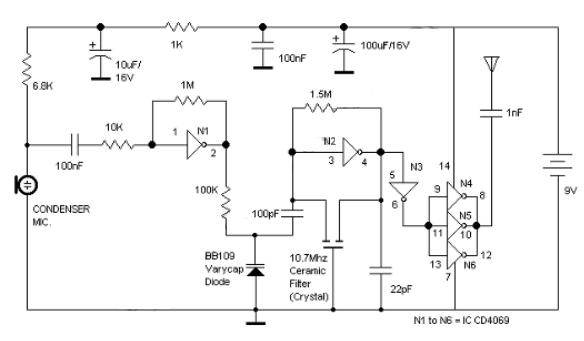
Logic Gates FM Transmitter Circuit
Logic Gates FM Transmitter Circuit Electronic Circuit Schematic Wiring Diagram.
The FM transmitter circuit utilizing logic gates is a fundamental electronic design that operates by modulating a carrier frequency with an audio signal. This circuit typically consists of various logic gates...

Simple Oscillator / Pipe Locator
Occasionally, there is a requirement to create a very basic oscillator. The circuit illustrated here is remarkably straightforward, utilizing only three components.
The described oscillator circuit typically consists of a resistor, a capacitor, and a single transistor. The operation of this...
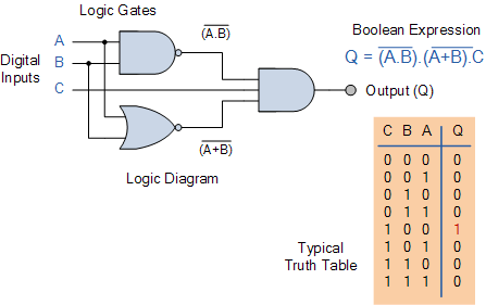
Combinational Logic Circuits using Logic Gates
Electronics tutorial on combinational logic circuits that utilize logic gates to create multiplexers, encoders, and solid-state switches.
Combinational logic circuits are fundamental components in digital electronics, characterized by their ability to produce outputs based solely on the current inputs, without any...

Logic Circuits Vs Transistor Power Circuits
Invert a signal to drive FETs with rapid rise and fall times. It was suggested to use an inverter (not a chip) instead of logic chips, which are designed to be either fully ON or OFF. The individual has prior...