


Electronic Slot Machine Circuit
#slot machine
#555 timer
#CMOS
#7-segment LED
#NAND gate
#display driver
#pulse generator
#IC
#gaming circuit

Description: The slot machine's realistic action is provided by seven integrated circuits (ICs) and three displays. Two 555 CMOS timer ICs generate pulses. IC1 generates the clock pulses for the entire electronic slot machine. The pulses are coupled from the output (pin 3) to the clock inputs of IC4, IC5, and IC6, which are the display-driver ICs. The displays are common-cathode 7-segment LED types, wired to display three different symbols: an L, a 7, and a bar. When all three displays show the same symbol, IC7 (a 4023 triple 3-input NAND gate) decodes a winner and sends a signal to pin 5 of IC3. This IC is a 4001 CMOS NOR gate that activates IC2, a 555 timer IC. IC2 produces the winner tone at its output, pin 3. Transistors Q4 through Q12 drive the common-cathode displays. An LED indicates the clock pulses, and a variable resistor is provided for each of these functions. Trimmer resistor P1 controls the overall clock rate, P2 controls the winner tone, and P3 controls the display brilliance.
The electronic slot machine circuit comprises a well-structured arrangement of components to facilitate its operation. The heart of the timing mechanism is IC1, a 555 timer configured in astable mode, generating a continuous stream of clock pulses. These pulses are essential for synchronizing the operations of the display driver ICs, specifically IC4, IC5, and IC6. Each of these ICs is responsible for driving one of the three common-cathode 7-segment LED displays, allowing the machine to represent various symbols visually.
The symbols displayed include an L, a 7, and a bar, which are fundamental to the slot machine's gameplay. The arrangement of these symbols is crucial; when all three displays align to show the same symbol, it indicates a winning condition. This is where IC7, a 4023 triple 3-input NAND gate, plays a pivotal role. It processes the signals from the display outputs and determines if a winning combination has occurred. Upon detecting a win, IC7 sends a signal to pin 5 of IC3, a 4001 CMOS NOR gate, which subsequently triggers the winning tone.
IC2, another 555 timer IC, is activated by the NOR gate output and generates the winning tone at its output pin 3. This audio feedback enhances the user experience by providing an audible indication of a successful outcome. To control the functionality and responsiveness of the circuit, several transistors (Q4 to Q12) are employed to drive the displays, ensuring bright and clear visibility of the symbols.
Additionally, the circuit includes an LED that visually indicates the clock pulses, providing a real-time status of the timing mechanism. To fine-tune the circuit performance, variable resistors are integrated into the design. Trimmer resistor P1 adjusts the overall clock rate, allowing for customization of the game speed. P2 modifies the winning tone's volume or duration, while P3 regulates the brightness of the displayed symbols, ensuring optimal visibility under various lighting conditions.
This comprehensive arrangement of ICs, displays, and control elements encapsulates the functionality of the electronic slot machine, providing an engaging and interactive gaming experience. The slot machine`s realistic action is provided by seven ICs and three displays, as shown. Two 555 CMOS timer ICs generate pulses. IC1 is used to generate the clock pulses for the entire electronic slot machine. The pulses are coupled from the output (pin 3) to the clock inputs of IC4, IC5, and 1C6, the display-driver ICs. The displays are common-cathode 7-segment LED types. They are wired to display three different symbols, an L, a 7, and bar, When all three displays show the same symbols, IC7 (a 4023 triple 3-iriput NAND gate) decodes a winner and sends a signal to pin 5 of IC3.
That IC is a 4001 CMOS NOR gate and it turns on IC2, a 555 timer IC. IC2 actually produces the winner tone on its output, pin 3. Transistors Q4 through Q12 are used to drive the common-cathode displays. An LED is used to indicate the clock pulses, and a variable resistor is provided for each of these functions. Trimmer resistor PI controls the overall clock rate, P2 controls the winner tone, and P3 controls the display brilliance.
The electronic slot machine circuit comprises a well-structured arrangement of components to facilitate its operation. The heart of the timing mechanism is IC1, a 555 timer configured in astable mode, generating a continuous stream of clock pulses. These pulses are essential for synchronizing the operations of the display driver ICs, specifically IC4, IC5, and IC6. Each of these ICs is responsible for driving one of the three common-cathode 7-segment LED displays, allowing the machine to represent various symbols visually.
The symbols displayed include an L, a 7, and a bar, which are fundamental to the slot machine's gameplay. The arrangement of these symbols is crucial; when all three displays align to show the same symbol, it indicates a winning condition. This is where IC7, a 4023 triple 3-input NAND gate, plays a pivotal role. It processes the signals from the display outputs and determines if a winning combination has occurred. Upon detecting a win, IC7 sends a signal to pin 5 of IC3, a 4001 CMOS NOR gate, which subsequently triggers the winning tone.
IC2, another 555 timer IC, is activated by the NOR gate output and generates the winning tone at its output pin 3. This audio feedback enhances the user experience by providing an audible indication of a successful outcome. To control the functionality and responsiveness of the circuit, several transistors (Q4 to Q12) are employed to drive the displays, ensuring bright and clear visibility of the symbols.
Additionally, the circuit includes an LED that visually indicates the clock pulses, providing a real-time status of the timing mechanism. To fine-tune the circuit performance, variable resistors are integrated into the design. Trimmer resistor P1 adjusts the overall clock rate, allowing for customization of the game speed. P2 modifies the winning tone's volume or duration, while P3 regulates the brightness of the displayed symbols, ensuring optimal visibility under various lighting conditions.
This comprehensive arrangement of ICs, displays, and control elements encapsulates the functionality of the electronic slot machine, providing an engaging and interactive gaming experience. The slot machine`s realistic action is provided by seven ICs and three displays, as shown. Two 555 CMOS timer ICs generate pulses. IC1 is used to generate the clock pulses for the entire electronic slot machine. The pulses are coupled from the output (pin 3) to the clock inputs of IC4, IC5, and 1C6, the display-driver ICs. The displays are common-cathode 7-segment LED types. They are wired to display three different symbols, an L, a 7, and bar, When all three displays show the same symbols, IC7 (a 4023 triple 3-iriput NAND gate) decodes a winner and sends a signal to pin 5 of IC3.
That IC is a 4001 CMOS NOR gate and it turns on IC2, a 555 timer IC. IC2 actually produces the winner tone on its output, pin 3. Transistors Q4 through Q12 are used to drive the common-cathode displays. An LED is used to indicate the clock pulses, and a variable resistor is provided for each of these functions. Trimmer resistor PI controls the overall clock rate, P2 controls the winner tone, and P3 controls the display brilliance.

The motorcycle anti-theft alarm (3)
This article introduces a motorcycle anti-theft alarm that utilizes the 555 timer integrated circuit. The alarm is activated when a thief attempts to move the motorcycle vertically. The circuit consists of a trigger circuit and an alarm circuit, as illustrated...

Positive Trigger Timer Circuit
This 555 timer is designed uniquely to provide a positive output through control over its reset pin. Typically, the 555 timer IC is triggered by applying a negative voltage.
The 555 timer is a versatile integrated circuit widely used in various...

Car Tachometer with 555 IC
Pulses are received by the timer from the distributor points. When the timer output is high, Meter M receives a calibrated current through R6. The meter does not...
The circuit described involves a timer that receives pulse signals from distributor points,...

Hee-haw-slren
A pair of timer integrated circuits (ICs) form the core of a circuit designed to simulate the distinctive warbling sound of a British police siren. One of the 555 timers, designated as U2, is configured as an astable multivibrator that...
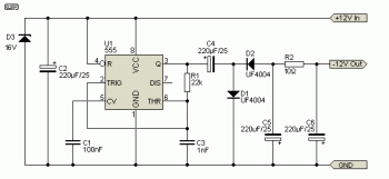
voltage double circuit with timer ic
This is a voltage doubling circuit built using the well-known timer IC 555. The circuit is straightforward and easy to construct. The construction is not critical. Rectifier diodes should be ultrafast (such as UF4004 or similar), or 1N4148 signal diodes...

astable circuit produce pulses
This circuit was first introduced by Signetics Corporation as the SE555/NE555 around 1971. Pin connections and functions are as follows: Pin 1 (Ground) is the most negative supply potential of the device, typically connected to circuit common when powered by...

Simple variable frequency oscillator
A simple variable frequency oscillator utilizing a 555 timer IC to generate a square wave frequency that can be adjusted using a potentiometer.
The circuit operates primarily on the principles of astable multivibrator configuration using the 555 timer IC, which is...

555 time control password electronic doorbell circuit
Figure 15-22 illustrates a doorbell system that consists of a monostable timing circuit, a password switch, a NAND gate circuit, and a sound output circuit. The operation of the circuit is designed such that when the password switch is pressed...

555 Timer as Monostable Multivibrator
A monostable multivibrator (MMV), commonly referred to as a one-shot multivibrator, is a pulse generator circuit where the pulse duration is determined by an externally connected resistor-capacitor (R-C) network to a 555 timer. In this configuration, one output state is...