


Signals Logic Tester Circuit Using Display 7 Segment
#logic tester
#7-segment display
#common cathode
#logic level
#H/L indicator
#digital circuit
#signal testing
#binary display

Description: This design features a signal logic tester that utilizes a common cathode seven-segment display. The display indicates a logic level "1" (represented by an "H" on the display) or a logic level "0" (represented by an "L" on the display). If an undefined logic level is detected, the display will show an alternative indication.
The signal logic tester circuit operates by monitoring input signals and interpreting their logic levels. The common cathode seven-segment display is connected to a microcontroller or logic circuit that interprets the incoming signals. When the input signal is at a high logic level (logic "1"), the corresponding segment of the display illuminates to show an "H." Conversely, when the input signal is at a low logic level (logic "0"), the display shows an "L."
In the case of an undefined logic level, which may occur due to floating inputs or noise, the circuit is designed to provide a distinct visual cue. This could be achieved by illuminating a specific segment of the display or by activating an additional indicator, such as an LED, to alert the user that the signal is not within the expected range.
The circuit design typically includes a resistor network to limit current to the display segments and ensure proper operation. A microcontroller may be programmed to read the input levels and control the display outputs accordingly. The design may also incorporate debouncing techniques to filter out noise and provide stable readings.
Overall, this signal logic tester serves as a valuable tool for electronics engineers and technicians, allowing for quick and effective monitoring of digital signals in various applications.Here s a design of signals logic tester that is using indicate on a common cathode seven-segment display, if entry is at logic level ""1"" (one H on the display) or logic level (one L on the display). If an undefined level is detected will display ..
The signal logic tester circuit operates by monitoring input signals and interpreting their logic levels. The common cathode seven-segment display is connected to a microcontroller or logic circuit that interprets the incoming signals. When the input signal is at a high logic level (logic "1"), the corresponding segment of the display illuminates to show an "H." Conversely, when the input signal is at a low logic level (logic "0"), the display shows an "L."
In the case of an undefined logic level, which may occur due to floating inputs or noise, the circuit is designed to provide a distinct visual cue. This could be achieved by illuminating a specific segment of the display or by activating an additional indicator, such as an LED, to alert the user that the signal is not within the expected range.
The circuit design typically includes a resistor network to limit current to the display segments and ensure proper operation. A microcontroller may be programmed to read the input levels and control the display outputs accordingly. The design may also incorporate debouncing techniques to filter out noise and provide stable readings.
Overall, this signal logic tester serves as a valuable tool for electronics engineers and technicians, allowing for quick and effective monitoring of digital signals in various applications.Here s a design of signals logic tester that is using indicate on a common cathode seven-segment display, if entry is at logic level ""1"" (one H on the display) or logic level (one L on the display). If an undefined level is detected will display ..
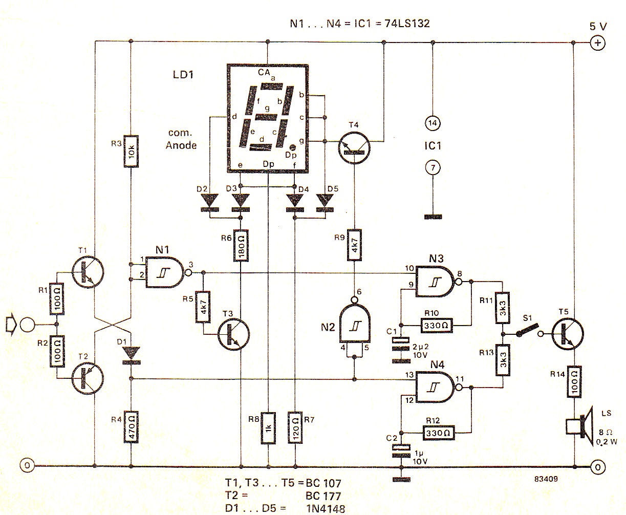
Digital High/Low Logic Tester Circuit diagram
When the input signal is at logic high (1), the display indicates `H`, and the loudspeaker emits a note that is one octave higher than the low tone. The operation of the circuit can be observed in the circuit diagram...

Logic Tester
The circuit consists of two comparators that operate with different reference voltages supplied by separate potential dividers. Divider R3/R4/R5 provides a voltage of approximately 40% of the supply voltage (Ucc) to pin 6 of IC1B and about 16% of Ucc...

Hi-Low Logic Digital tester
This tester, the logic level digital signals indicate on a 7-segment display. The display shows an H as the input signal is high. When the signal is low, the display shows an L on. If the input is open, the...

Audible Logic Tester Circuit
The tester provides an audible indication of the logic level of the signal presented to its input. A logic high is indicated by a high tone, a logic low is indicated by a low tone, and oscillation is indicated by...

Audible-logic-tester
This tester provides an audible indication of the logic level of the signal presented to its input. A logic high is indicated by a high tone, a logic low is indicated by a low tone, and oscillation is indicated by...

7 segment Display
Multiplexed 7-Segment Display PCB. The display PCB consists of four MAN72 7-segment common-anode displays.
The multiplexed 7-segment display PCB is designed for efficient visual representation of numerical data. Each MAN72 7-segment display is a common-anode type, meaning that the anode connections...

random number generator game
This electronic game simulates a one-arm bandit game, appealing to electronics hobbyists. When toggle switch S1 is in the 'run' position, all segments of the 7-segment displays (DIS1 through DIS3) illuminate. Upon switching S1 from 'run' to 'stop', the displayed...

Interfacing to 7-Segment Displays
In industrial PLC applications, one of the older yet simpler methods of displaying numeric information involves utilizing one or more 7-segment numeric displays connected to an output card of a PLC. While it is feasible to construct such a display...

7 segment rolling display using pc
It is entirely feasible and acceptable to control various outputs while sitting at a PC terminal. A simple hardware circuit and software are utilized to interface with a 7-segment rolling display. The printer port of a PC provides a set...