


Tone probe for testing digital ics
#tone probe
#digital ICs
#signal testing
#low-pitched tone
#high-pitched tone
#voltage levels
#logic probe
#testing tool
#circuit debugging
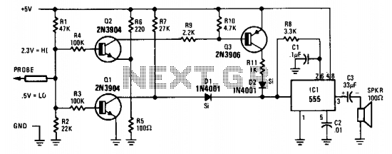
Description: The probe's input circuit detects the signal condition and generates a low-pitched tone for low-level signals (below 0.8 V) or a high-pitched tone for high-level signals (above 2 V). The tone probe employs sound to indicate the status of the signal being measured.
The probe's input circuit is designed to monitor electrical signals and provide auditory feedback regarding their levels. It operates by utilizing a comparator circuit that evaluates the input voltage against predefined thresholds. When the input voltage falls below 0.8 V, the circuit activates a low-frequency oscillator, producing a low-pitched tone. Conversely, when the signal exceeds 2 V, the circuit switches to a high-frequency oscillator, generating a high-pitched tone.
The circuit typically consists of several key components: a voltage divider to scale the input signal, an operational amplifier configured as a comparator, and a piezoelectric speaker or buzzer for sound output. The voltage divider ensures that the input signal is within the operational range of the comparator, while the operational amplifier provides the necessary gain and switching capability.
Additionally, the design may include a microcontroller to enhance functionality, allowing for adjustable thresholds, signal processing, and possibly visual indicators, such as LEDs, to accompany the audible tones. This combination of sound and visual feedback aids in the effective monitoring of signal conditions in various electronic applications, such as troubleshooting and maintenance tasks. The tone probe serves as a valuable tool for engineers and technicians, providing immediate and intuitive feedback on signal status. The probe's input circuit senses the condition of the signal and produces either a low-pitched tone for low-level signals (less than 0.8 V) or a high-pitched tone for high-level signals (greater than 2 V). The tone probe uses sound to tell the status of the signal being probed.
The probe's input circuit is designed to monitor electrical signals and provide auditory feedback regarding their levels. It operates by utilizing a comparator circuit that evaluates the input voltage against predefined thresholds. When the input voltage falls below 0.8 V, the circuit activates a low-frequency oscillator, producing a low-pitched tone. Conversely, when the signal exceeds 2 V, the circuit switches to a high-frequency oscillator, generating a high-pitched tone.
The circuit typically consists of several key components: a voltage divider to scale the input signal, an operational amplifier configured as a comparator, and a piezoelectric speaker or buzzer for sound output. The voltage divider ensures that the input signal is within the operational range of the comparator, while the operational amplifier provides the necessary gain and switching capability.
Additionally, the design may include a microcontroller to enhance functionality, allowing for adjustable thresholds, signal processing, and possibly visual indicators, such as LEDs, to accompany the audible tones. This combination of sound and visual feedback aids in the effective monitoring of signal conditions in various electronic applications, such as troubleshooting and maintenance tasks. The tone probe serves as a valuable tool for engineers and technicians, providing immediate and intuitive feedback on signal status. The probe's input circuit senses the condition of the signal and produces either a low-pitched tone for low-level signals (less than 0.8 V) or a high-pitched tone for high-level signals (greater than 2 V). The tone probe uses sound to tell the status of the signal being probed.

S1Ngle-Ic Logic Probe
This logic probe utilizes a CD4009 CMOS hex inverter. The high-input impedance characteristic of CMOS technology prevents loading of the circuit under test. Since the output of the inverters is not defined at either a high or low level with...

Audible Logic Probe
The NE556 timer IC can be utilized to create an audible indication of the static state of terminals in digital logic. An audible logic probe can be particularly beneficial when visual observation is not feasible.
The NE556 timer is a dual...

Pulse Reading Logic Probe
This circuit uses LEDs to display logic states for high, low, rising pulse, and falling pulse. It is generally useful for debugging logic circuitry.
The described circuit employs light-emitting diodes (LEDs) as visual indicators for various logic states in digital electronics....

Many Logic probe circuit ideas
A logic probe is a useful tool for checking digital circuits. It functions similarly to a meter, which is employed to measure power in electrical circuits.
A logic probe is an essential diagnostic instrument in digital electronics, designed to analyze and...

Simple logic probe
If the probe is connected to logic 0, Q1 will be activated, illuminating D1. When connected to logic 1, Q2 will be activated, illuminating D2. Any NPN or PNP transistors can be used for Q1 and Q2. Likewise, D1 and...

LOGIC PROBE with PULSER
This project is a combination Logic Probe and Logic Pulser. It is capable of testing all sorts of digital and microcomputer projects. You will find it extremely handy when designing a project as the golden rule is to test everything...

Logic Probe With Sound
This logic probe can be selected to operate on TTL or CMOS logic levels, depending on switch S1. A string of resistors associated with switch S1 sets the threshold levels for a window comparator comprising IC1a and IC1b. Depending on...

Audible Logic Probe with LM339
When testing circuits with a logic probe, it is sometimes difficult to watch the LEDs on the probe to determine the logic state. With this probe, the logic states are audible. This probe is designed for TTL circuits only but...

Logic Probe
By connecting this circuit to a powered logic device, an indication of its status can be obtained. If the circuit is open, neither of the test lamps will illuminate. If the circuit is grounded, the low (or zero) lamp will...