



Logic probe
The probe indicates a high or low at 70% and 30% of V+ (5 to 12 V). One section of the voltage comparator (LM393) senses V in over 70% of supply and the second ...

Logic test probe with memory
There are two switches: a memory disable switch and a pulse polarity switch. Memory disable is a push-button that resets the memory to the low state when depres...

Logic probe
Transistors Q1 and Q2 form a buffer, providing the probe with a reasonable input impedance. Q3 and Q4 form a level detecting circuit. As the voltage across the ...

Audible ttl probe
When the probe is in contact with a TTL low (0) the probe emits a low note. With a TTL high (1), a high note is emitted...

Cmos logic probe
The logic probe can indicate four input states, as follows: floating input—all LEDs off...

Logic probe yields three discrete states
The circuit uses a dual LED. When power is applied to the probe throughthe power leads, and the input is touched to a low level or ground, Ql is cut off. This w...

Overvoltage protection for logic
Zener diode ZD1 senses the supply, and should the supply rise above 6 V, Ql will turn on. In turn, Q2 conducts clamping the rail. Subsequent events depend on th...

Shift register driver
A16 V power supply can be synthesized as shown using IN1692 rectifiers. A shift pulse input saturates the 2N2714 depriving the Darlington combination (2N2714 an...

Negative to positive supply logic level shifter
This simple circuit provides for level shifting from any logic function (such as MOS) operating from minus to ground supply to any logic level (such as TTL) ope...

Programmable gate
This gate converts an AND gate or an OR gate by applying a logic 1 on the function input/The logic design uses 8 two-input NAND gates...

Light activated logic circuits
These circuits illustrate some of the common logic functions...

Shift register
The shift pulse amplitude is less than 15 volts. If a stage is off, the shift pulse will not be coupled to the next stage. If it is on, the diode will conduct a...

Windicator
Two TTL ICs and a handful of other components are all that is needed for a circuit that will indicate which of four buttons was pressed first, as well as lock o...

Heads or tails
This ultra-simple heads or tails indicator uses a single 4077 and no capacitor. The circuit is normally in a latched bistable mode; when the switch is closed th...

Toss-a-coin binary box
Circuit uses an astable multivibrator to vary the heads-or-tails condition, and a flip-flop to store the condition given by the multivibrator...

Electronic dice
Six LEDs are arranged to produce a display the same as the dots on a dice. When PBI is depressed, the display is blanked and the oscillator (ICl a, b, c) clocks...
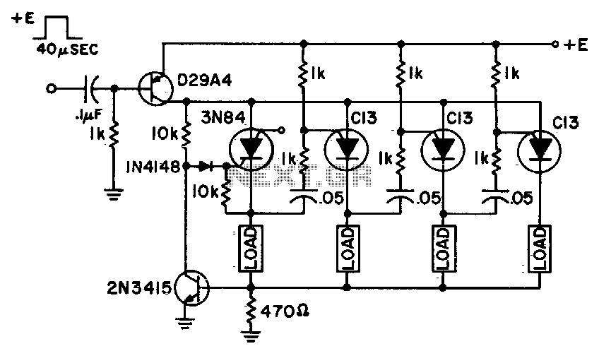
Low cost ring counter
This ring counter makes an efficient, low cost circuit featuring automatic resetting via the first stage 3N84...
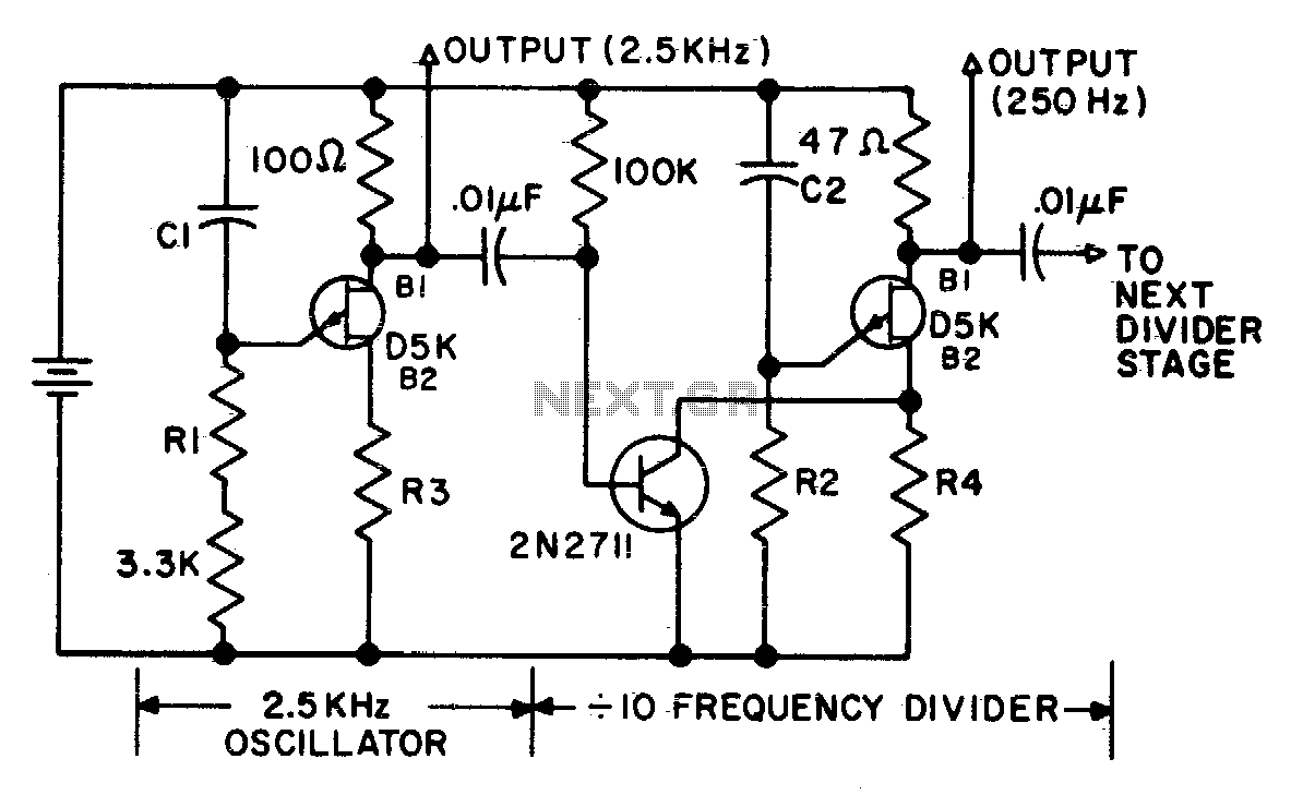
Decade frequency divider
In the next stage, the product of R2 and C2 should be 10 x that of the preceding stage (±2%). R2 should be between 27K and 10 M...
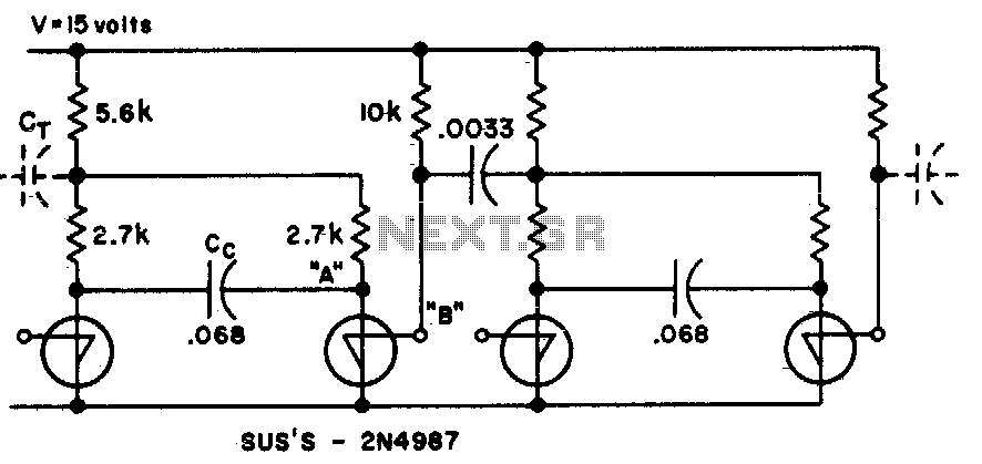
Binary divider chain
This circuit uses fewer components than transistor flip flops...
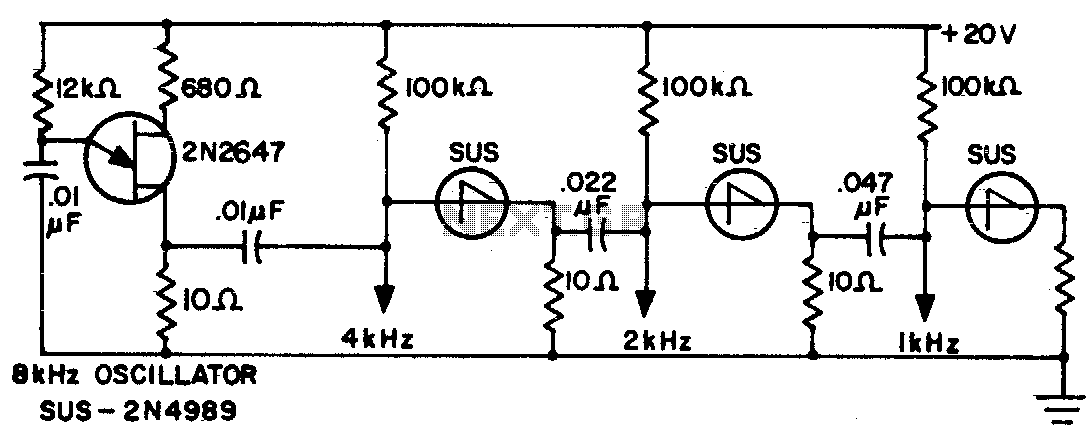
Frequency divider chain
Sawtooth output from each stage is one half frequency...