



Cmos programmable divide-by-n counter
A single connection change permits division by any integer between 2 and 10. The RCA CD4017A Johnson decade counter is shown connected as a divide by 7 counter....

Edge detector
This circuit provides a short negative-going output pulse for every positive-going edge at the input. The input waveform is coupled to the input by capacitor C;...

Multiplexed bcd-to-parallel bcd converter
Converter consists of four quad bistable latches activated in the proper sequence by the digit strobe output of the LD110. The complemented outputs (Q) of the q...

Bcd-to-analog converter
This circuit will convert four-bit BCD into a variable voltage from 0-9 V in 1 V steps. The SN74141 is a Nixie driver, and has ten open-collector outputs. These...

Cmos mixer
Four inputs can be mixed by duplicating the circuit to the left of C3 and using the fourth gate of ICI. Two gates are used in a touch-operated switching circuit...

Tape recorder position indicator-controller
This circuit is representative of the many applications of up/down counting in monitoring dimensional position. In the tape recorder application, the LOAD REGIS...

Siren uses TTL gates
The siren consists of two oscillators which generate the tones. A third oscillator is used to switch the others on and off alternately, giving the two-tone effe...

7400 Siren
Two NAND gates are used for the oscillator, and two as the control. If the two-tone speed needs to be altered, the 220 µ capacitors can be changed Oarger for...

Non-integer programmable pulse divider
In applications where the period of the input pulses is uneven and the divider is required to cover a wide range of frequencies, the non-integer programmable pu...
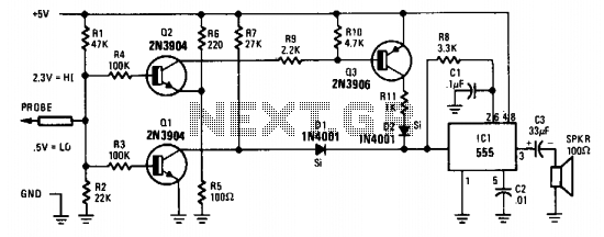
Tone probe for testing digital ics
The probe's input circuit senses the condition of the signal and produces either a low-pitched tone for low-level signals (less than 0.8 V) or a high-pitched t...

Simple phase detector
The operation of the circuit is like an enabled inverter, that is, the output Y = B provided A is high. If A is low, output is low (independent of the state of ...

Analog multiplexer
This adapter circuit, based on a dual four-channel analog multiplexer handles digital signals to at least 1 MHz, and analog signals at least through the audio r...

Power-on reset
This type of reset pulse is ideally provided by this circuit. Because of the high input impedance of the Schmitt trigger, long reset pulse times may be achieve...

Shift register
The shift pulse amplitude is less than 15 volts. If a stage is off, the shift pulse will not be coupled to the next stage. If it is on, the diode will conduct t...

4-Channel commutator
The DS7800 voltage translator is a monolithic device that provides from 10 V to -20 V gate drive to the JFETs while at the same time providing DTL/TTL logic co...

Led indicates logic states
The LED is the CSL310L which contains a red LED and a green LED connected back to back and mounted close together in a single moulding. The LED can emit red or^...

audible logic pulses
This circuit is useful for monitoring slow logic pulses as a keying monitor or digital clock alarm. The Schmitt trigger is connected as an oscillator....

12-Bit dac with variable step size
The step size of the converter is variable by selection of the high order data bits. The first DAC, A, has a stable reference current supplied via the 10.24 V r...

Two 8-bit dacs make a 12-bit dac
Two MC1408—8-bit D/A converters, A and in the circuit diagram, are used. The four least-significant bits of A are tied to zero. The four most significan...

Pulse coincidence detector
Unless inputs A and (2- to 3-V amplitude) occur simultaneously no voltage exists across Rl. Less than 1 microsecond overlap is sufficient to trigger the scs.
...