


250W Inverter Circuit

Description: A 555 timer (IC1) generates a 120-Hz signal that is fed to a CD4013BE flip-flop (IC1-a), which divides the input frequency by two to generate a 60-Hz clocking frequency for the FET array (Q1 through Q6). Transformer T1 is a 12-/24-V center-tapped 60-Hz transformer of suitable size.
The circuit utilizes a 555 timer integrated circuit configured in astable mode to produce a square wave output at a frequency of 120 Hz. The frequency is determined by the resistor and capacitor values connected to the timer. This output signal is then directed to a CD4013BE dual D-type flip-flop, specifically using one of its flip-flops (IC1-a). The flip-flop operates as a frequency divider, effectively halving the input frequency, thus generating a 60 Hz clock signal.
The generated 60 Hz clock signal is crucial for controlling an array of Field Effect Transistors (FETs) labeled Q1 through Q6. These FETs can be used in various applications, such as switching or amplifying signals, depending on the circuit's design. The FET array is likely configured to respond to the clock signal, enabling synchronized operation of the connected loads.
In addition to these components, the circuit includes a transformer (T1) that steps down the voltage from a higher AC voltage source to a lower voltage level suitable for the circuit's operation. The transformer is specified as a center-tapped 12-/24-V transformer designed to operate at a 60 Hz frequency. The center-tap configuration allows for the generation of two different voltage levels, which can be beneficial for powering different parts of the circuit or for providing a reference ground.
This circuit design highlights the integration of timing, frequency division, and power management, making it suitable for applications that require precise timing control and efficient switching capabilities. Proper selection of component values and ratings is essential to ensure reliable performance and to meet the specific requirements of the intended application. A 555 timer (IC1) generates a 120-Hz signal that is fed to a CD4013BE flip-flop (ICl-a), which divides the input frequency by two to generate a 60-Hz clocking frequency for the FET array (Ql through Q6). Transformer Tl is a 12-/24-V center-tapped 60-Hz transformer of suitable size.
The circuit utilizes a 555 timer integrated circuit configured in astable mode to produce a square wave output at a frequency of 120 Hz. The frequency is determined by the resistor and capacitor values connected to the timer. This output signal is then directed to a CD4013BE dual D-type flip-flop, specifically using one of its flip-flops (IC1-a). The flip-flop operates as a frequency divider, effectively halving the input frequency, thus generating a 60 Hz clock signal.
The generated 60 Hz clock signal is crucial for controlling an array of Field Effect Transistors (FETs) labeled Q1 through Q6. These FETs can be used in various applications, such as switching or amplifying signals, depending on the circuit's design. The FET array is likely configured to respond to the clock signal, enabling synchronized operation of the connected loads.
In addition to these components, the circuit includes a transformer (T1) that steps down the voltage from a higher AC voltage source to a lower voltage level suitable for the circuit's operation. The transformer is specified as a center-tapped 12-/24-V transformer designed to operate at a 60 Hz frequency. The center-tap configuration allows for the generation of two different voltage levels, which can be beneficial for powering different parts of the circuit or for providing a reference ground.
This circuit design highlights the integration of timing, frequency division, and power management, making it suitable for applications that require precise timing control and efficient switching capabilities. Proper selection of component values and ratings is essential to ensure reliable performance and to meet the specific requirements of the intended application. A 555 timer (IC1) generates a 120-Hz signal that is fed to a CD4013BE flip-flop (ICl-a), which divides the input frequency by two to generate a 60-Hz clocking frequency for the FET array (Ql through Q6). Transformer Tl is a 12-/24-V center-tapped 60-Hz transformer of suitable size.
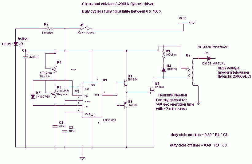
Flyback Transformer circuit with 555
The 555 is wired as an astable and the capacitor is charged only through the 4.7Kohm trimmer (notice the diode) and discharged only through the 2.2 Kohm trimmer, making the duty cycle fully adjustable. The square wave is then fed...

Inverted 555 Timer Circuit
When using the 555 timer, the output polarity often appears to be incorrect, as the 555 typically cannot produce a duty cycle of less than 50%. This inverted 555 circuit is capable of generating duty cycles below 50%. The functionality...

laser controlled on off switch
This circuit is designed around a 555 timer and utilizes a minimal number of components. Its simplicity allows even beginners to easily assemble and operate it as a control device. A readily available laser pointer can be used to activate...

555 Timer astable oscillator circuit
The 555 timer circuit has unsteady open and closing times that are independent of one another. One time constant is given by 1.1RcC2, while another time constant is defined as 1.1RcC3. The free-running period is the sum of these time...

555 transistor characteristic curve tracer circuit diagram
The transistor characteristic curve tracer circuit depicted in Figure 555 illustrates the characteristics of a transistor. It utilizes two voltages: a step wave applied to the base (b) to generate different base currents (Ib), and a sawtooth waveform at the...

555 timer compo entry 2
This entry describes a four-step sequencer that controls an Atari Punk synth, accompanied by a grayscale NTSC video visualization of the output audio. The system is constructed using two 558 quad-timers and two 556 dual-timers. The video quality may not...

555 stepper pulse generator
The 555 Stepper Pulse Generator kit will help you with the pulse required to drive your favorite DC Servo Motor application. This kit uses the famous 555 timer IC for generating the Stepping Pulse. More: Input - 5 - 12...

0-1 hours of power a circuit diagram of the timing of the AC power supply
The provided information indicates that when the power supply operates between 0 to 1 hour, an AC circuit diagram is established using a 555 timer configured as a one-hour timer. The relay utilized is a J 212 IRC MR312C with...

driving a relay
The 555 timer will activate a relay. When pins 2 and 6 are connected as an input, the chip requires only about 1 µA to activate the output. This is equivalent to a gain of approximately 200 million and represents...