


0-1 hours of power a circuit diagram of the timing of the AC power supply
#555 timer
#AC power supply
#relay
#timing circuit
#delay circuit
#power control
#circuit diagram
#electronics

Description: The provided information indicates that when the power supply operates between 0 to 1 hour, an AC circuit diagram is established using a 555 timer configured as a one-hour timer. The relay utilized is a J 212 IRC MR312C with a coil impedance that requires a current of less than 200 mA at 12V. The delay time can be adjusted between 3 to 58 minutes by altering the values of resistor R2 and capacitor C1. The pin configuration for the NE555 timer in this setup is as follows: pin 8 (VCC), pin 3 (output), pin 4 (reset), pin 2 (trigger), pin 1 (ground), pin 7 (discharge), and pin 6 (threshold).
The circuit utilizes a 555 timer IC, which is widely recognized for its versatility in timing applications. In this configuration, the 555 timer is set up in monostable mode, meaning it generates a single output pulse when triggered. The duration of this pulse, which corresponds to the timer's delay, is governed by the time constant determined by the resistor R2 and capacitor C1.
The relay, specifically the J 212 IRC MR312C, is employed to switch AC loads. When the 555 timer is triggered, it energizes the relay coil, allowing current to flow through the relay contacts and subsequently activating the connected load. The specified coil current of less than 200 mA ensures compatibility with the 12V power supply, making it suitable for various applications.
For users seeking to modify the delay time, adjustments to the resistance of R2 or the capacitance of C1 will result in different timing intervals. The relationship between resistance, capacitance, and time delay can be described by the formula:
\[ T = 1.1 \times R \times C \]
Where T is the time delay in seconds, R is the resistance in ohms, and C is the capacitance in farads. By selecting appropriate values for R2 and C1, a wide range of timing options can be achieved, from the minimum of 3 minutes to the maximum of 58 minutes.
The pin configuration of the NE555 timer is crucial for proper operation. Pin 8 is connected to the positive supply voltage (VCC), while pin 1 is grounded. Pin 2 is the trigger input, which initiates the timing cycle when a low signal is applied. Pin 3 provides the output signal to control the relay, and pin 4 is connected to the reset pin to allow for manual resetting of the timer. Pin 6 serves as the threshold input, and pin 7 is the discharge pin that discharges the timing capacitor once the timing interval is complete.
This circuit design is ideal for applications requiring timed control of AC devices, such as lighting systems, motor controls, or any other equipment that necessitates a delay before activation. As shown when the power supply is 0 to 1 hour, set the AC circuit diagram 555 constituted within one hour timer, J 212 IRC MR312C relay coil impedance, or current of less than 200mA 12V relay. FIG parameters, the delay time is 3 to 58 minutes. If you want to get other time range, change the value of R2 and C1. Clockwise as seen from the top of the foot NE555R order 8,3,4,2,1,7 and 6.
The circuit utilizes a 555 timer IC, which is widely recognized for its versatility in timing applications. In this configuration, the 555 timer is set up in monostable mode, meaning it generates a single output pulse when triggered. The duration of this pulse, which corresponds to the timer's delay, is governed by the time constant determined by the resistor R2 and capacitor C1.
The relay, specifically the J 212 IRC MR312C, is employed to switch AC loads. When the 555 timer is triggered, it energizes the relay coil, allowing current to flow through the relay contacts and subsequently activating the connected load. The specified coil current of less than 200 mA ensures compatibility with the 12V power supply, making it suitable for various applications.
For users seeking to modify the delay time, adjustments to the resistance of R2 or the capacitance of C1 will result in different timing intervals. The relationship between resistance, capacitance, and time delay can be described by the formula:
\[ T = 1.1 \times R \times C \]
Where T is the time delay in seconds, R is the resistance in ohms, and C is the capacitance in farads. By selecting appropriate values for R2 and C1, a wide range of timing options can be achieved, from the minimum of 3 minutes to the maximum of 58 minutes.
The pin configuration of the NE555 timer is crucial for proper operation. Pin 8 is connected to the positive supply voltage (VCC), while pin 1 is grounded. Pin 2 is the trigger input, which initiates the timing cycle when a low signal is applied. Pin 3 provides the output signal to control the relay, and pin 4 is connected to the reset pin to allow for manual resetting of the timer. Pin 6 serves as the threshold input, and pin 7 is the discharge pin that discharges the timing capacitor once the timing interval is complete.
This circuit design is ideal for applications requiring timed control of AC devices, such as lighting systems, motor controls, or any other equipment that necessitates a delay before activation. As shown when the power supply is 0 to 1 hour, set the AC circuit diagram 555 constituted within one hour timer, J 212 IRC MR312C relay coil impedance, or current of less than 200mA 12V relay. FIG parameters, the delay time is 3 to 58 minutes. If you want to get other time range, change the value of R2 and C1. Clockwise as seen from the top of the foot NE555R order 8,3,4,2,1,7 and 6.

Fake Car Alarm Circuit 555 tutorial
This page outlines how to create a simple theft deterrent that can be quite effective. The concept involves using a flashing red LED to indicate that the vehicle is protected. This device serves to safeguard the car from potential thieves...

250W Inverter Circuit
A 555 timer (IC1) generates a 120-Hz signal that is fed to a CD4013BE flip-flop (IC1-a), which divides the input frequency by two to generate a 60-Hz clocking frequency for the FET array (Q1 through Q6). Transformer T1 is a...

555 Rock lantern controller circuit diagram
The controller features a buck rectifier circuit utilizing a 555 multivibrator, designed for controlling approximately 220V, 5W low-power parallel lights or 6 to 12V small bulb series. The 555 timer, along with components D3, D4, RP1, and C2, forms an...

relay circuit 9 second led timer
This circuit provides a visual 9-second delay using 10 LEDs before closing a 12-volt relay. When the switch is closed, the 4017 decade counter will reset to zero, illuminating the LED connected to pin 3. The output at pin 3...

555 Low Voltage Operation
There have been stories regarding the suboptimal performance of the 555 timer IC when operated below a supply voltage (Vcc) of 5V, prompting an investigation into potential improvements for its operation.
The 555 timer IC is a versatile device commonly used...

LED Flasher Using 555 IC
This LED flasher circuit is similar to the previous transistor-based LED flasher but utilizes a 555 integrated circuit as the primary component. The schematic diagram illustrates an LED flasher circuit that produces alternating LED flashing, with distinct flashing periods for...

sound detector switch
When the 555 IC goes into timing mode (triggered by an output signal from the sound detector amplifier), the timer's output (pin 3) is set to HIGH for a duration set by C2 and R2. Adjusting R1 will adjust how...
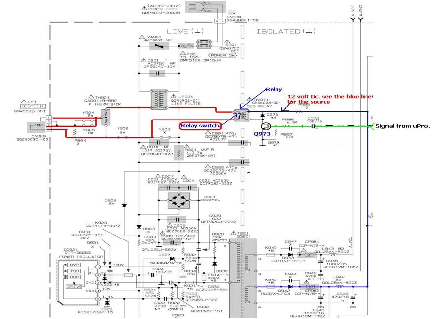
relay found in switch mode power supply
In the example above, a low voltage (12V DC) is utilized to activate a relay that switches a 240V AC main circuit. It is important to note that there is no electrical connection between the two circuits within the relay;...

555 timer
The 555 timer IC was first introduced around 1971 by the Signetics Corporation as the SE555/NE555 and was referred to as "The IC Time Machine." It was the first commercially available timer IC, providing circuit designers and hobbyists with an...