


Dot matrix LED display
#LED matrix
#microcontroller
#PIC18F252
#display control
#dot matrix
#PCB design
#LED driver
#matrix display
#embedded control


Description: The device comprises two parts: LED control board and LED display board. The two PCBs are designed to fit together one behind the other using two sets of dual row connectors and 4 spacers. One of these connectors is used for the electrical connections, while the other is only used as a mechanical connecting element. The core of the device is microcontroller PIC18F252 (U9). It controls all the functions of the device, generates the overall algorithm to control the LED matrix. LEDs are connected in matrix 40x7. The columns tie together the cathodes of the LEDs and rows tie the LEDs anodes. The LED matrix is controlled dynamically in row by row. To save space and number of components, the LEDs are driven with specialized LED driver STP16CP05 (U101-U103), produced by ST Microelectronics. Each of these ICs contains a 16-bit serial-in, parallel-out shift register, latch register, and 16 constant current output channels. Outputs are open drain type, allowing connection of a load supplied with up to 20V supply voltage. The constant current for all outputs varies from 5 to 100 mA and is set from an external resistor (R115-R117). In this application, the three LED drivers are connected in a cascade and controlled from the microcontroller over SPI protocol. The microcontroller sends a 48-bit word, controlling one row at a time. The 40 LSB represent LED states (1-On, 0-Off) in the row and control their cathodes. The 7 MSB control the anodes through the 7 driver transistors (VT101 - VT107). The 40th bit remains unused. The microcontroller sends the 48-bit word every 1 ms.
There are 7 cycles to display each row plus an extra blank cycle, used to process temperature measurements. Thus, the refresh rate of the display is 125Hz. To control the display brightness, the "outputs enable" (OE) pin is used. Each row cycle begins with a logical 0 on the OE pin (outputs are enabled). The duration of an enabled signal changes depending on the desired brightness, using the microcontroller's on-chip PWM module.
LED dot matrix display 40x7;
- Display of clock, calendar, inside and outside temperature, text messages;
- Automatic Daylight Savings Time;
- Capability of keeping the real-time clock working correctly for more than one week without power supply;
- Inside temperature measurement (0 ÷ +75) °C, ±0.5 °C accuracy;
- Outside temperature measurement (-40 ÷ +75) °C, ±0.5 °C accuracy;
- Supports static and running messages with different effects;
- Full Cyrillic and special symbols support;
- Memory for 10 messages, each including up to 250 symbols;
- Automatic brightness control;
- IR remote control for settings messages select;
- Power supply: 12 ÷ 24V DC;
- Front panel dimensions 305 x 69 mm.
The LED display system operates with a dual-board configuration where the LED control board interfaces with the LED display board through dual row connectors, facilitating both electrical connections and structural integrity. The microcontroller PIC18F252 serves as the central processing unit, executing control algorithms to manage the LED matrix configuration. The matrix is structured in a 40x7 format, with cathodes connected in columns and anodes in rows, allowing for an efficient dynamic control method.
To minimize component count and space on the PCB, the design incorporates three STP16CP05 LED driver ICs, which facilitate the driving of the matrix with constant current outputs. The open-drain outputs of these drivers enable flexible voltage supply options, accommodating loads up to 20V, while the external resistors (R115-R117) provide adjustable current settings for each output channel.
Communication between the microcontroller and the LED drivers occurs via the SPI protocol, where a 48-bit data word is transmitted to control the LED states for each row sequentially. The arrangement of the LED outputs does not follow a linear mapping to the driver pins, which is addressed through software to ensure that the physical layout corresponds accurately to the intended display output.
The system is designed to refresh the display at a rate of 125Hz, balancing the need for responsiveness with the processing overhead required for temperature measurement and display updates. Automatic brightness control is achieved through PWM modulation, allowing the user to adjust display visibility based on ambient light conditions.
The device features a comprehensive set of functionalities, including real-time clock capabilities, temperature measurements, and the ability to display messages with various effects. It also supports a wide range of character sets and has memory for storing multiple messages. Power supply requirements range from 12V to 24V DC, and the physical dimensions of the front panel have been optimized for user interaction and visibility.The device comprises two parts: LED control board and LED display board. The two PCBs are designed to fit together one behind the other using two sets of dual row connectors and 4 spacers. One of this connector is used for the electrical connections, while the other is only used as a mechanical connecting element.
The core of the device is microcontroller PIC18F252 (U9). It controls all the functions of the device, generates the overall algorithm to control the LED matrix. LEDs are connected in matrix 40x7. The columns tie together the cathodes of the LEDs and rows tie the LEDs anodes. The LED matrix is controlled dynamically in row by row. To safe space and number of components, the LEDs are driven with specialized LED driver STP16CP05 (U101-U103), produced by ST Microelectronics. Each of these IC contain 16-bit serial-in, parallel-out shift register, latch register and 16 constant current output channels.
Outputs are open drain type, allowing connection of a load supplied with up to 20V supply voltage. The constant current for all outputs varies from 5 to 100 mA and is set from an external resistor (R115-R117). In this application, the three LED drivers are connected in a cascade and controlled from the microcontroller over SPI protocol.
The microcontroller sends a 48-bit word, controlling one row at the time. The 40 LSB represent LED states (1-On, 0-Off) in the row and control their cathodes. The 7 MSB control the anodes through the 7 driver transistors (VT101 - VT107). The 40th bit remains unused. The microcontroller sends the 48-bit word every 1 ms. There are 7 cycles to display each row plus an extra blank cycle, used to process temperature measurements. Thus, the refresh rate of the display is 125Hz. To control the display brightness is used the "outputs enable" (OE) pin. Each row cycle begins with logical 0 on the OE pin (outputs are enabled). The duration of an enabled signal changes depending on the desired brightness, using the microcontroller's on-chip PWM module.
You should note that numbers of columns and rows are not sequential to the corresponding pins of the ICs (U101-U103). This aims to simplify the design of PCB. The LEDs' corresponding bits are rearranged by software to fit with their physical order. LED dot matrix display 40x7; - Display of clock, calendar, inside and outside temperature, text messages; - Automatic Daylight Savings Time; - Capability of keeping the real time clock working correctly for more than one week without power supply; - Inside temperature measurement (0 ÷ +75) °C, ±0.5 °C accuracy; - Outside temperature measurement (-40 ÷ +75) °C, ±0.5 °C accuracy; - Supports static and running messages with different effects; - Full Cyrillic and special symbols supports; - Memory for 10 messages, each including up to 250 symbols; - Automatic brightness control; - IR remote control for settings messages select; - Power supply: 12 ÷ 24V DC; - Front panel dimensions 305 x 69 mm.
There are 7 cycles to display each row plus an extra blank cycle, used to process temperature measurements. Thus, the refresh rate of the display is 125Hz. To control the display brightness, the "outputs enable" (OE) pin is used. Each row cycle begins with a logical 0 on the OE pin (outputs are enabled). The duration of an enabled signal changes depending on the desired brightness, using the microcontroller's on-chip PWM module.
LED dot matrix display 40x7;
- Display of clock, calendar, inside and outside temperature, text messages;
- Automatic Daylight Savings Time;
- Capability of keeping the real-time clock working correctly for more than one week without power supply;
- Inside temperature measurement (0 ÷ +75) °C, ±0.5 °C accuracy;
- Outside temperature measurement (-40 ÷ +75) °C, ±0.5 °C accuracy;
- Supports static and running messages with different effects;
- Full Cyrillic and special symbols support;
- Memory for 10 messages, each including up to 250 symbols;
- Automatic brightness control;
- IR remote control for settings messages select;
- Power supply: 12 ÷ 24V DC;
- Front panel dimensions 305 x 69 mm.
The LED display system operates with a dual-board configuration where the LED control board interfaces with the LED display board through dual row connectors, facilitating both electrical connections and structural integrity. The microcontroller PIC18F252 serves as the central processing unit, executing control algorithms to manage the LED matrix configuration. The matrix is structured in a 40x7 format, with cathodes connected in columns and anodes in rows, allowing for an efficient dynamic control method.
To minimize component count and space on the PCB, the design incorporates three STP16CP05 LED driver ICs, which facilitate the driving of the matrix with constant current outputs. The open-drain outputs of these drivers enable flexible voltage supply options, accommodating loads up to 20V, while the external resistors (R115-R117) provide adjustable current settings for each output channel.
Communication between the microcontroller and the LED drivers occurs via the SPI protocol, where a 48-bit data word is transmitted to control the LED states for each row sequentially. The arrangement of the LED outputs does not follow a linear mapping to the driver pins, which is addressed through software to ensure that the physical layout corresponds accurately to the intended display output.
The system is designed to refresh the display at a rate of 125Hz, balancing the need for responsiveness with the processing overhead required for temperature measurement and display updates. Automatic brightness control is achieved through PWM modulation, allowing the user to adjust display visibility based on ambient light conditions.
The device features a comprehensive set of functionalities, including real-time clock capabilities, temperature measurements, and the ability to display messages with various effects. It also supports a wide range of character sets and has memory for storing multiple messages. Power supply requirements range from 12V to 24V DC, and the physical dimensions of the front panel have been optimized for user interaction and visibility.The device comprises two parts: LED control board and LED display board. The two PCBs are designed to fit together one behind the other using two sets of dual row connectors and 4 spacers. One of this connector is used for the electrical connections, while the other is only used as a mechanical connecting element.
The core of the device is microcontroller PIC18F252 (U9). It controls all the functions of the device, generates the overall algorithm to control the LED matrix. LEDs are connected in matrix 40x7. The columns tie together the cathodes of the LEDs and rows tie the LEDs anodes. The LED matrix is controlled dynamically in row by row. To safe space and number of components, the LEDs are driven with specialized LED driver STP16CP05 (U101-U103), produced by ST Microelectronics. Each of these IC contain 16-bit serial-in, parallel-out shift register, latch register and 16 constant current output channels.
Outputs are open drain type, allowing connection of a load supplied with up to 20V supply voltage. The constant current for all outputs varies from 5 to 100 mA and is set from an external resistor (R115-R117). In this application, the three LED drivers are connected in a cascade and controlled from the microcontroller over SPI protocol.
The microcontroller sends a 48-bit word, controlling one row at the time. The 40 LSB represent LED states (1-On, 0-Off) in the row and control their cathodes. The 7 MSB control the anodes through the 7 driver transistors (VT101 - VT107). The 40th bit remains unused. The microcontroller sends the 48-bit word every 1 ms. There are 7 cycles to display each row plus an extra blank cycle, used to process temperature measurements. Thus, the refresh rate of the display is 125Hz. To control the display brightness is used the "outputs enable" (OE) pin. Each row cycle begins with logical 0 on the OE pin (outputs are enabled). The duration of an enabled signal changes depending on the desired brightness, using the microcontroller's on-chip PWM module.
You should note that numbers of columns and rows are not sequential to the corresponding pins of the ICs (U101-U103). This aims to simplify the design of PCB. The LEDs' corresponding bits are rearranged by software to fit with their physical order. LED dot matrix display 40x7; - Display of clock, calendar, inside and outside temperature, text messages; - Automatic Daylight Savings Time; - Capability of keeping the real time clock working correctly for more than one week without power supply; - Inside temperature measurement (0 ÷ +75) °C, ±0.5 °C accuracy; - Outside temperature measurement (-40 ÷ +75) °C, ±0.5 °C accuracy; - Supports static and running messages with different effects; - Full Cyrillic and special symbols supports; - Memory for 10 messages, each including up to 250 symbols; - Automatic brightness control; - IR remote control for settings messages select; - Power supply: 12 ÷ 24V DC; - Front panel dimensions 305 x 69 mm.

Cheapest High power LED driver circuit diagram
If the reader arrived here via Google, they may have encountered other circuits for high-power LED driving that include many components such as inductors, operational amplifiers, various regulator ICs, transistor feedback networks, and microcontrollers. While those circuits tend to be...

Buck-Boost High Power White LED Driver
The LTC3453 is a synchronous buck-boost DC/DC converter optimized for driving up to 4 white LEDs at a combined current of up to 500mA from a single Li-Ion battery input. The regulator operates in either synchronous buck, synchronous boost, or...

Night Light Saver
A Microchip PIC12C508 8-pin CMOS microcontroller controls a night light, turning it on and off at preset times every day. It is designed to save energy, produce no electromagnetic interference (EMI), and operate without batteries, featuring a built-in lamp fixture...

PCBoardMaker3
BoardMaker3 is an integrated environment for the design of Printed circuit boards, offering a comprehensive set of tools that allow schematic entry, Spice simulation, 3D viewing and an Autorouter Interface. With a Customised graphics engine and a user configureable interface...
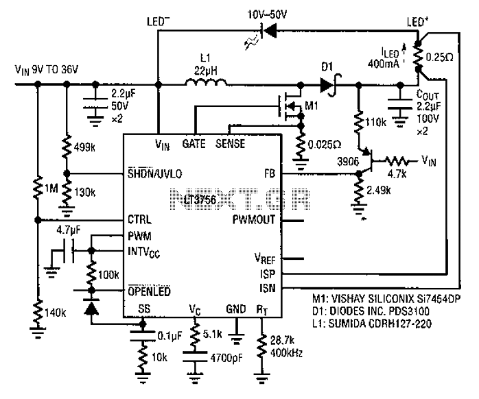
Based LT3756 buck - boost mode drive circuit diagram
Common LED driver requirements include a wide and overlapping range of LED string voltages and input voltages. Many designers prefer to use an LED driver circuit that accommodates various battery power sources and multiple LED strings. This universal configuration may...
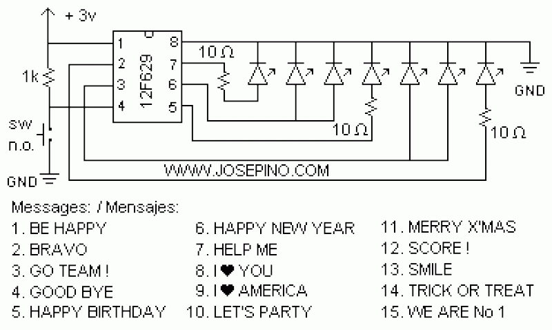
ON/OFF button using Microcontrollers
Using a switch to power up your microcontroller projects may not be a good idea if you need to "wake" the PIC during some events. For example: A metal detector sends a pulse indicating a car is ready to enter...

Water Level controller
The microcontroller-based water level controller and motor protector manages the on and off states of the motor based on the water level in the overhead tank (OHT). It regulates the tank's water level through a microcontroller, thereby providing automatic protection...

Sprint-Layout
Design your own Printed Circuit Boards Sprint-Layout is a simple but powerful tool to create layouts for single-sided and double-sided PCBs (Printed Circuit Boards). More: The software comes along with all functions that are necessary for board design. Even professional...

Microcontroller Relay Driver and Interface
Many microcontroller designs typically integrate various interfacing methods. A microcontroller (µC) system can be viewed as a system that reads from inputs.
Microcontroller systems are versatile platforms that facilitate the integration of multiple interfacing methods to interact with various peripherals and...