


Esposito Wang
#ultra bright LEDs
#high power LEDs
#multi-channel
#LED flash
#maximum current
#LED array
#precise control
#test light
#LED driver
#brightness control

Description: This project builds upon the 2012 LED Flicker project. The objective is to create an ultra-bright, multi-channel test light using high-power LEDs driven to their maximum rated current with precise control. By utilizing an array of seven ultra-bright LEDs, the aim is to produce a world-class LED flash. Instead of employing PWM control, which flickers between OFF and ON states, this project focuses on designing a system that maintains a constant current through each LED. The design simulates a camera flash using supercapacitors charged by a wall adapter or benchtop power supply. Each LED will be pulsed with a maximum of 1 amp of current. The LED array module consists of seven different LEDs, with each LED flashing sequentially to ensure that no two LEDs are illuminated simultaneously. The duration of each LED's illumination and the interval between flashes are adjustable for user convenience. Modifications can be made to allow the system to be powered by alkaline or lithium-ion batteries for compact and portable use. To achieve this, a system is constructed using one current driver circuit for each LED, an Arduino microcontroller to control each channel, and a supercapacitor circuit to supply the necessary current. This system is charged by a high-power, efficient charging circuit that maintains the capacitors in a charged state, ready to power the flash. To ensure stable light output, the LEDs must be driven by a constant current. The circuit employs a feedback resistor and BJT combination to sense the current flowing through the LED, which feeds back to the MOSFET gate, controlling its voltage and thus the current flowing through it. This design allows approximately 1A of current to flow through each LED. The key concept is to drive the LEDs and FETs with a constant current, making their light output insensitive to supply voltage. Simulations were conducted to analyze the system's behavior with the proposed circuit parameters, revealing that the Luxeon array LEDs exhibit a relatively shallow turn-on slope, leading to voltage sensitivity despite the constant current drive. To mitigate this, a supply voltage range was selected to keep the LEDs within their saturation region. Careful selection of feedback resistance is crucial for current control, as it regulates the maximum current in the circuit. Given the high current design (1A), multi-watt power resistors are necessary for current limiting to prevent damage from power dissipation. Feedback resistance was determined through multiple simulations in LTSpice to ensure the circuit operates as expected and to identify optimal resistance values for both feedback and input resistors (at the FET gate). Seven copies of the current driver circuit will be assembled, each driving one LED in the array, with control signals routed to the FET gates from the Arduino microcontroller. Ideally, the system should be capable of driving multiple LEDs simultaneously. To accommodate higher drive currents (multi-amp) when triggering seven or more 1A LEDs concurrently, a power supply circuit based on 50F supercapacitors was developed. These capacitors can be easily charged using a conventional voltage regulator to approximate an ideal voltage source. However, this approach is time-consuming for fully charging the capacitors. Consequently, a current-controlled power supply was designed. The circuit is straightforward, utilizing an LM317 adjustable linear regulator as a regulated voltage supply, which can be replaced by a switching regulator for improved efficiency.
The circuit design consists of several key components, including the Arduino microcontroller, which serves as the control unit for the LED array. Each LED is connected to a dedicated current driver circuit, which includes a MOSFET for switching and a feedback loop to maintain constant current. The supercapacitors are connected in parallel to provide the necessary energy storage, enabling rapid discharge during the LED flash events. The LM317 voltage regulator is configured to output a stable voltage that charges the supercapacitors.
The feedback mechanism is essential for maintaining the desired current through each LED. The BJT and feedback resistor work in tandem to monitor the current and adjust the gate voltage of the MOSFET accordingly. This setup ensures that the current remains consistent even with variations in supply voltage, thus providing reliable performance across different operating conditions.
For the adjustable timing of the LED flashes, the Arduino microcontroller is programmed to control the duration and interval of each LED's illumination. The flexibility in timing allows for various applications, from testing to creative lighting effects.
Safety considerations are paramount, especially due to the high currents involved. The use of multi-watt resistors for current limiting is critical to prevent overheating and potential damage to the circuit. Additionally, the choice of supercapacitors should consider their voltage ratings and discharge characteristics to ensure they can handle the required load without failure.
Overall, this project not only enhances the original LED Flicker concept but also expands its functionality and application potential through careful design and component selection. The integration of modern microcontroller technology with high-power LED driving techniques represents a significant advancement in LED flash systems.This projects builds upon the 2012 LED Flicker project. The goal is to build an ultra bright, multi-channel test light using extremely high power LEDs driven to their maximum rated current, and controlled precisely. By driving an array of 7 ultra bright LEDs, we aim to produce a world class LED flash. Instead of controlling the LEDs via PWMs, whi ch has properties of flicking between OFF and ON states, the goal of this project is to design a system that provides a constant current through each LED. The design mimics a camera flash with the use of super capacitors charged by a wall wart power adapter or benchtop supply.
Each LED will be pulsed with a max of 1 amp of current. There are 7 different LEDs on the LED array module and each LED is flashed so that no two LEDs are on at the same time. The time duration that the LED is on and the time interval between LED flashes are adjustable to allow for ease of use.
Modifications can be made so that this design can be charged with Alkaline or Lithium-Ion batteries to make the entire system compact and portable. In order to achieve this goal, we built a system using one current driver circuit for each LED, an Arduino micro-controller to switch each channel, and a super-capacitor circuit to provide the necessary current.
This system is charged by a high power, efficient charging circuit which keeps the capacitors charged and ready to drive the flash. To get a system that produces a stable light output, the LED must be driven by a constant current. An approach to get a constant current is using the circuit to the right. The way this circuit works is that the feedback resistor and BJT combination sense the amount of current flowing though the LED and feed this signal back to the MOSFET gate controlling its voltage and hence the current flowing through it.
This design allows approximately ~1A of current to flow through the LED. The key idea was drive the LEDs and FETs with a constant current making their light output insensitive to supply voltage. Simulations were performed to analyze the behavior of the system with the proposed circuit parameters, and it was found that the LEDs in the Luxeon array have a relatively shallow turn on slope, introducing voltage sensitivity despite the constant current drive of the supply.
In order to remedy this, we had to choose a supply voltage range that would keep the LEDs in their own `saturation` region. For current control, the key parameter that must be selected with caution is the feedback resistance since that controls the maximum current flowing through the circuit.
Given that this is a high current (1Amp) design, multi-watt power resistors must be used for the current limiters ensure that the power dissipated in them does not damage the circuit. To determine what feedback resistance we needed, we performed several simulations in LTSpice to verify that the circuit will work the way we expect it to and the optimal resistance parameters for the feedback and input resistors (at the gate of the FET).
Seven copies of this circuit will be assembled, one to drive each LED in the array, with the seven control signals routed to the gates of the FETs from the Arduino microcontroller. Ideally, the system should be able to drive more than one LED in the array at once. In order to support a much higher (multi-amp) drive current, caused by triggering 7 or more 1A LEDs at once, we had to build a supply circuit that was based around a collection of 50F super-capacitors.
These capacitors can be charged simply, using a conventional voltage regulator to approximate an ideal voltage source. This is problematic, however, as it will take an extremely long time to charge the capacitors fully. As a result, we designed a current controlled power supply. The circuit is fairly straightforward - an LM317 adjustable linear regulator acts as a regulated voltage supply.
This supply could easily be replaced by a swit
The circuit design consists of several key components, including the Arduino microcontroller, which serves as the control unit for the LED array. Each LED is connected to a dedicated current driver circuit, which includes a MOSFET for switching and a feedback loop to maintain constant current. The supercapacitors are connected in parallel to provide the necessary energy storage, enabling rapid discharge during the LED flash events. The LM317 voltage regulator is configured to output a stable voltage that charges the supercapacitors.
The feedback mechanism is essential for maintaining the desired current through each LED. The BJT and feedback resistor work in tandem to monitor the current and adjust the gate voltage of the MOSFET accordingly. This setup ensures that the current remains consistent even with variations in supply voltage, thus providing reliable performance across different operating conditions.
For the adjustable timing of the LED flashes, the Arduino microcontroller is programmed to control the duration and interval of each LED's illumination. The flexibility in timing allows for various applications, from testing to creative lighting effects.
Safety considerations are paramount, especially due to the high currents involved. The use of multi-watt resistors for current limiting is critical to prevent overheating and potential damage to the circuit. Additionally, the choice of supercapacitors should consider their voltage ratings and discharge characteristics to ensure they can handle the required load without failure.
Overall, this project not only enhances the original LED Flicker concept but also expands its functionality and application potential through careful design and component selection. The integration of modern microcontroller technology with high-power LED driving techniques represents a significant advancement in LED flash systems.This projects builds upon the 2012 LED Flicker project. The goal is to build an ultra bright, multi-channel test light using extremely high power LEDs driven to their maximum rated current, and controlled precisely. By driving an array of 7 ultra bright LEDs, we aim to produce a world class LED flash. Instead of controlling the LEDs via PWMs, whi ch has properties of flicking between OFF and ON states, the goal of this project is to design a system that provides a constant current through each LED. The design mimics a camera flash with the use of super capacitors charged by a wall wart power adapter or benchtop supply.
Each LED will be pulsed with a max of 1 amp of current. There are 7 different LEDs on the LED array module and each LED is flashed so that no two LEDs are on at the same time. The time duration that the LED is on and the time interval between LED flashes are adjustable to allow for ease of use.
Modifications can be made so that this design can be charged with Alkaline or Lithium-Ion batteries to make the entire system compact and portable. In order to achieve this goal, we built a system using one current driver circuit for each LED, an Arduino micro-controller to switch each channel, and a super-capacitor circuit to provide the necessary current.
This system is charged by a high power, efficient charging circuit which keeps the capacitors charged and ready to drive the flash. To get a system that produces a stable light output, the LED must be driven by a constant current. An approach to get a constant current is using the circuit to the right. The way this circuit works is that the feedback resistor and BJT combination sense the amount of current flowing though the LED and feed this signal back to the MOSFET gate controlling its voltage and hence the current flowing through it.
This design allows approximately ~1A of current to flow through the LED. The key idea was drive the LEDs and FETs with a constant current making their light output insensitive to supply voltage. Simulations were performed to analyze the behavior of the system with the proposed circuit parameters, and it was found that the LEDs in the Luxeon array have a relatively shallow turn on slope, introducing voltage sensitivity despite the constant current drive of the supply.
In order to remedy this, we had to choose a supply voltage range that would keep the LEDs in their own `saturation` region. For current control, the key parameter that must be selected with caution is the feedback resistance since that controls the maximum current flowing through the circuit.
Given that this is a high current (1Amp) design, multi-watt power resistors must be used for the current limiters ensure that the power dissipated in them does not damage the circuit. To determine what feedback resistance we needed, we performed several simulations in LTSpice to verify that the circuit will work the way we expect it to and the optimal resistance parameters for the feedback and input resistors (at the gate of the FET).
Seven copies of this circuit will be assembled, one to drive each LED in the array, with the seven control signals routed to the gates of the FETs from the Arduino microcontroller. Ideally, the system should be able to drive more than one LED in the array at once. In order to support a much higher (multi-amp) drive current, caused by triggering 7 or more 1A LEDs at once, we had to build a supply circuit that was based around a collection of 50F super-capacitors.
These capacitors can be charged simply, using a conventional voltage regulator to approximate an ideal voltage source. This is problematic, however, as it will take an extremely long time to charge the capacitors fully. As a result, we designed a current controlled power supply. The circuit is fairly straightforward - an LM317 adjustable linear regulator acts as a regulated voltage supply.
This supply could easily be replaced by a swit

Buck-Based LED Drivers
The first switching LED driver to be examined is the buck converter. The buck converter is the simplest type of switching driver and serves as a step-down converter for applications where the load voltage is typically no more than approximately...

230V LED DRIVER CIRCUIT
This document presents a 230V LED driver circuit that operates without a transformer. The circuit utilizes five LEDs, although the number can be increased as desired. The absence of transformers significantly reduces both the cost and size of the circuit....

white led driver by lt1618
The LT1618 not only offers an accurate input current limit but can also be utilized to deliver a regulated output current suitable for current-source applications.
The LT1618 is a precision current limiting device that can be effectively employed in various electronic...

White LED Step-Up Converters with Schottky
The LT3465/LT3465A are step-up DC/DC converters designed to drive up to six LEDs in series from a Li-Ion cell. Series connection of the LEDs provides identical LED currents and eliminates the need for ballast resistors. These devices integrate the Schottky...

Constant Current Source LED Drive
This is a constant current source LED driver. When the upper NPN transistor is activated by a voltage through a 4.7kΩ resistor, the LED lights up. It is assumed that the lower NPN transistor is absent. The current flowing through...

high voltage white led driver
This high-voltage white LED driver electronic circuit schematic utilizes the NCP5021 integrated circuit from On Semiconductor. The NCP5021 is designed with an ambient light sensing feature and can drive up to eight LEDs in series for portable backlight applications. The...

Discrete High Current Switch Mode LED Driver
This is a discrete high-current switch-mode LED driver circuit. The fundamental principle of this circuit is based on the buck-converter topology. The efficiency of this circuit is 80%.
The discrete high-current switch-mode LED driver circuit utilizes a buck converter configuration to...
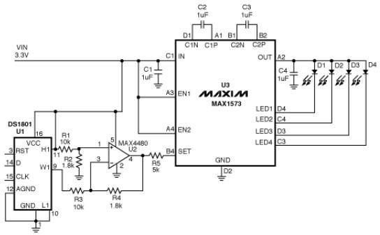
MAX1573 white led driver electronic project schematic
This white LED driver circuit operates up to four white LEDs in parallel from a 3.3V power source, adjusting the total LED current from 1mA to 106mA in 64 steps of 1dB each. The brightness control of the LEDs is...

4 LED Driver for Handset LCD Backlight Circuit
The ZXLD1100 is a PFM flyback DC to DC boost converter that operates in discontinuous mode. The following circuit diagram illustrates the configuration of four LED drivers for handset LCD backlighting using this device. The ZXLD1100 is designed to drive...