


Line-operated-power-outage-light
#emergency lighting
#power outage
#phototransistor
#neon light
#6-V lamp
#ambient light
#circuit design
#lighting
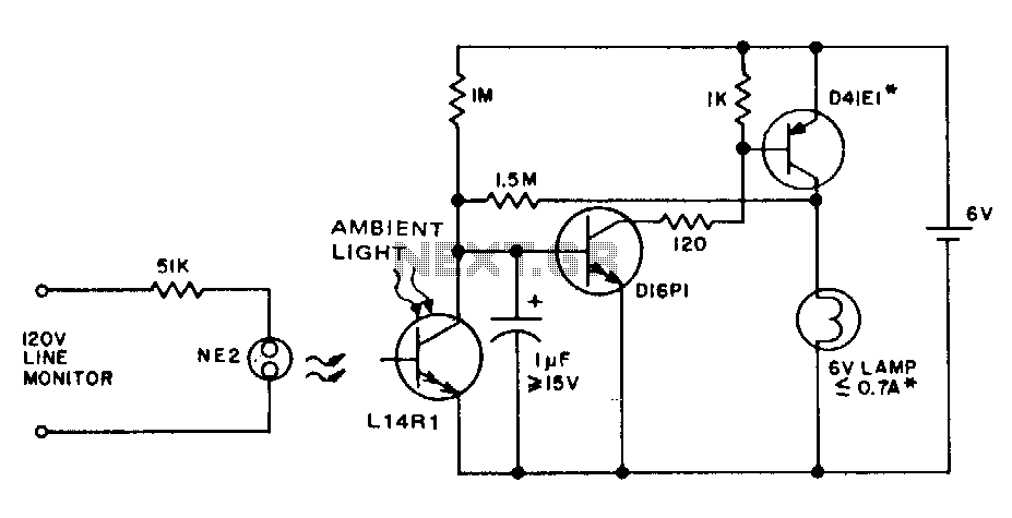
Description: This circuit provides emergency lighting during a power outage. The phototransistor should be positioned to maximize the coupling of both neon light and ambient light into the pellet, without allowing self-illumination from the 6-V lamp. Many circuits of this type also use line voltage to charge the battery.
The described emergency lighting circuit is designed to activate during power outages, ensuring illumination in critical situations. The core component of this circuit is a phototransistor, which plays a pivotal role in detecting ambient light levels. The positioning of the phototransistor is crucial; it must be oriented to effectively capture both neon and ambient light while preventing interference from the self-illumination of a 6-V lamp. This careful arrangement helps maintain the functionality of the emergency lighting system without unintended activation.
In addition to its primary function, the circuit is capable of utilizing line voltage for battery charging. This feature allows the battery to remain charged during normal operation, ensuring that it is ready to power the emergency lighting system when required. The integration of a charging circuit typically involves a rectifier to convert AC to DC, followed by a voltage regulator to maintain appropriate charging levels for the battery.
The overall design of the circuit should include protective elements, such as fuses or circuit breakers, to safeguard against overcurrent conditions that may arise during charging or operation. Furthermore, the circuit may incorporate a relay or a transistor switch to control the activation of the 6-V lamp based on the phototransistor's readings, ensuring that the lamp only illuminates when necessary.
In summary, this emergency lighting circuit is a well-thought-out design that combines the functionality of light detection, battery charging, and emergency illumination, making it a reliable solution for power outage scenarios.This circuit provides emergency lighting during a power outage. The phototransistor should be positioned to maximize coupling of both neon light and ambient light into the pellet, without allowing self-illumination from the 6-V lamp. Many circuits of this type also use line voltage to charge the battery.
The described emergency lighting circuit is designed to activate during power outages, ensuring illumination in critical situations. The core component of this circuit is a phototransistor, which plays a pivotal role in detecting ambient light levels. The positioning of the phototransistor is crucial; it must be oriented to effectively capture both neon and ambient light while preventing interference from the self-illumination of a 6-V lamp. This careful arrangement helps maintain the functionality of the emergency lighting system without unintended activation.
In addition to its primary function, the circuit is capable of utilizing line voltage for battery charging. This feature allows the battery to remain charged during normal operation, ensuring that it is ready to power the emergency lighting system when required. The integration of a charging circuit typically involves a rectifier to convert AC to DC, followed by a voltage regulator to maintain appropriate charging levels for the battery.
The overall design of the circuit should include protective elements, such as fuses or circuit breakers, to safeguard against overcurrent conditions that may arise during charging or operation. Furthermore, the circuit may incorporate a relay or a transistor switch to control the activation of the 6-V lamp based on the phototransistor's readings, ensuring that the lamp only illuminates when necessary.
In summary, this emergency lighting circuit is a well-thought-out design that combines the functionality of light detection, battery charging, and emergency illumination, making it a reliable solution for power outage scenarios.This circuit provides emergency lighting during a power outage. The phototransistor should be positioned to maximize coupling of both neon light and ambient light into the pellet, without allowing self-illumination from the 6-V lamp. Many circuits of this type also use line voltage to charge the battery.

Pulse meter circuit
The input capacitor for the phototransistor at the bottom is responsible for feeding the operational amplifier (op-amp). However, the output from the phototransistor consistently remains between ground (GND) and the supply voltage (Vcc). The necessity for an input capacitor arises...

Phototransistor for High Impedance Voltmeter
This circuit is designed to provide an affordable method for creating a high impedance voltmeter using a low-cost analog or digital multimeter. The circuit is specifically intended for testing phototransistors. When measuring voltages in high resistance circuits, the resistance of...

LIGHT METER WITH LED READOUT
The phototransistor Q1 (Radio Shack 276-130) activates a voltage change across resistor R2, which is then amplified by an operational amplifier (op-amp). The output from the op-amp drives an array of five LEDs, creating a bar graph voltage indicator. To...

Light intensity 10 a 10LX twilight light control switch circuit diagram
A bridge input circuit utilizing a phototransistor BPY62 and a power operational amplifier is capable of controlling power loads up to 8.5 kW. It features a voltage divider composed of two 10 kΩ resistors, creating a midpoint connection. The operational...
Photoelectric controller circuit immunity
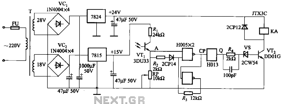
The circuit features a robust anti-jamming capability, making it suitable for demanding applications. It includes a phototransistor (VTi), a Schmitt trigger (H005), a JK flip-flop (H013), a power amplifier circuit, a relay (KA), and various actuators and other components. The...

Simple Photoelectric Light Controller
A phototransistor detects daylight. At dusk, it stops conducting, and Rl biases Q2, activating Kl, which turns on the light. At dawn, Ql begins to conduct, cutting off Q2. Kl deactivates, and the light turns off.
The circuit utilizes a phototransistor...

Blackout emergency lights circuit 3
Figure 283 illustrates a blackout emergency lighting controller designed for straightforward external installation with two leads. This controller can directly replace the P Chan Tong Ge opening. Under normal power conditions, it functions like a conventional switch to control lamp...

Automatic emergency lighting circuit
An automatic emergency lighting circuit is presented, suitable for self-installation in households. It utilizes smaller components, resulting in a lower cost. Under normal conditions, the 220V AC mains voltage is reduced by capacitor C1, and then processed through a half-wave...

Electronic Projects
This program includes circuit design CAD, simulation, and auto-routing PC layout. PSPICE is also utilized at Unisys, which offers more capabilities but costs six times as much and requires annual renewal. With these requirements and others in mind, a variation...