


Fuel-cell battery tester
#fuel cell
#battery tester
#constant current load
#dynamic load
#TMOS Power FET
#measurement
#instrumentation
#power devices

Description: This circuit was designed for testing fuel cells, but it could also be used for testing batteries under a constant current load. It provides a dynamic, constant current load, eliminating the need to manually adjust the load to maintain a constant load. For fuel cell applications, the load must be able to absorb 20-40 A, and since a single cell develops only 0.5 to 1.0 V, bipolar power devices (such as a Darlington) are impractical. Therefore, this dynamic load was designed with a TMOS Power FET (Q2). With switch SI in position 1, emitter follower Q1 and resistor R1 establish the current level for the load. In position 2, an external voltage can be applied to control the current level. Operational amplifier U1 drives TMOS device Q1, which sets the load current seen by the fuel cell or battery. The voltage drop across R15, which is related to the load current, is then applied to U2, whose output is fed back to U1. Thus, if the voltage across R15 tends to change, feedback to the negative input of U1 causes that voltage (and the load current) to remain constant. Adjustment of R13 controls the volts/amp of feedback. The VOUT point is used to monitor the system.
The circuit operates by utilizing a dynamic load configuration that allows for precise control over the current drawn from the fuel cell or battery under test. The TMOS Power FET (Q2) acts as the primary switching element, providing efficient operation at the required current levels. When switch SI is set to position 1, the emitter follower configuration formed by Q1 and R1 establishes a stable current reference. This configuration is crucial for maintaining the desired load current without manual intervention.
In position 2, the circuit can accept an external voltage signal to modulate the load current, providing flexibility for various testing scenarios. The operational amplifier U1 plays a critical role in regulating the load current. It receives feedback from the voltage drop across R15, which is directly proportional to the current flowing through the load. The feedback loop ensures that any variations in load current are corrected promptly, maintaining a constant current output to the fuel cell or battery.
The feedback mechanism is designed such that any increase or decrease in the voltage across R15 results in a corresponding adjustment in the output of U1. This maintains the load current at a constant value, which is essential for accurate testing of the device under evaluation. The adjustment potentiometer R13 allows for calibration of the feedback sensitivity, enabling the user to fine-tune the relationship between the voltage and current in the system.
The VOUT point serves as a monitoring output, providing a means to observe the performance of the circuit during operation. This allows for real-time assessment of the load conditions and the overall health of the fuel cell or battery being tested. The design is optimized for high current applications, making it suitable for rigorous testing environments where reliable performance and accurate measurements are paramount.This circuit was designed for testing fuel cells, but it could also be used for testing batteries under a constant current load. It provides a dynamic, constant current load, eliminating the need to manually adjust the load to maintain a constant load.
For fuel cell application, the load must be able to absorb 20-40 A, and since a single cell develops only 0.5 to 1.0 V, bipolar power devices (such as a Darlington) are impractical. Therefore, this dynamic load was designed with a TMOS Power FET (Q2). With switch SI in position 1, emitter follower Ql and Rl establish the current level for the load. In position 2, an external voltage can be applied to control the current level. Operational amplifier Ul drives TMOS device Ql, which sets the load current seen by the fuel cell or battery. The voltage drop across R15, which is related to the load current, is then applied to U2, whose output is fed back to Ul.
Thus, if the voltage across R15 would tend to change, feedback to the minus input of Ul causes that voltage (and the load current) to remain constant. Adjustment of R13 controls the volts/amp of feedback. The V0UT point is used to monitor the system.
The circuit operates by utilizing a dynamic load configuration that allows for precise control over the current drawn from the fuel cell or battery under test. The TMOS Power FET (Q2) acts as the primary switching element, providing efficient operation at the required current levels. When switch SI is set to position 1, the emitter follower configuration formed by Q1 and R1 establishes a stable current reference. This configuration is crucial for maintaining the desired load current without manual intervention.
In position 2, the circuit can accept an external voltage signal to modulate the load current, providing flexibility for various testing scenarios. The operational amplifier U1 plays a critical role in regulating the load current. It receives feedback from the voltage drop across R15, which is directly proportional to the current flowing through the load. The feedback loop ensures that any variations in load current are corrected promptly, maintaining a constant current output to the fuel cell or battery.
The feedback mechanism is designed such that any increase or decrease in the voltage across R15 results in a corresponding adjustment in the output of U1. This maintains the load current at a constant value, which is essential for accurate testing of the device under evaluation. The adjustment potentiometer R13 allows for calibration of the feedback sensitivity, enabling the user to fine-tune the relationship between the voltage and current in the system.
The VOUT point serves as a monitoring output, providing a means to observe the performance of the circuit during operation. This allows for real-time assessment of the load conditions and the overall health of the fuel cell or battery being tested. The design is optimized for high current applications, making it suitable for rigorous testing environments where reliable performance and accurate measurements are paramount.This circuit was designed for testing fuel cells, but it could also be used for testing batteries under a constant current load. It provides a dynamic, constant current load, eliminating the need to manually adjust the load to maintain a constant load.
For fuel cell application, the load must be able to absorb 20-40 A, and since a single cell develops only 0.5 to 1.0 V, bipolar power devices (such as a Darlington) are impractical. Therefore, this dynamic load was designed with a TMOS Power FET (Q2). With switch SI in position 1, emitter follower Ql and Rl establish the current level for the load. In position 2, an external voltage can be applied to control the current level. Operational amplifier Ul drives TMOS device Ql, which sets the load current seen by the fuel cell or battery. The voltage drop across R15, which is related to the load current, is then applied to U2, whose output is fed back to Ul.
Thus, if the voltage across R15 would tend to change, feedback to the minus input of Ul causes that voltage (and the load current) to remain constant. Adjustment of R13 controls the volts/amp of feedback. The V0UT point is used to monitor the system.
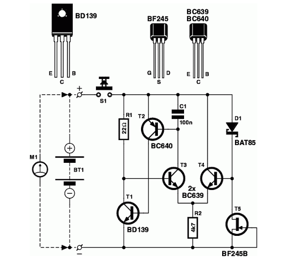
Battery Tester Circuit Schematic
Is the battery empty, or is there something wrong with the device? This question often arises when troubleshooting a battery-powered device, such as a Walkman.
When diagnosing issues with battery-powered devices, it is essential to systematically evaluate both the battery and...

Battery Tester Circuit Schematic
Determining whether a battery is empty or if there is a fault with a device can be challenging when a battery-powered device, such as a Walkman, fails to power on. Before seeking professional repair, it is advisable to test the...

ProfiLab-Expert 4.0
The ProfiLab-Expert software allows you to develop your own digital or analogue measuring technology projects. It doesn't matter if you want to create analogue measurements or digital controls - you can realize it all. And for all this you don't...
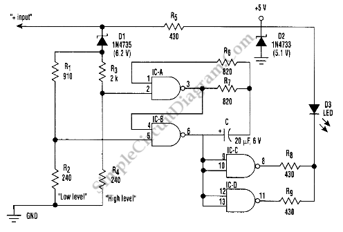
Battery Tester/Indicator/Monitor
This is a battery tester circuit. This circuit is used to indicate whether the level of a battery voltage is normal, under-voltage, or over-voltage.
The battery tester circuit is designed to assess the voltage level of a battery and provide a...

Car Battery Tester For Cranking Amps Circuit
This circuit measures the cold cranking amps of a battery by discharging the surface charge and then assessing the internal resistance. This method provides a more accurate measurement than merely observing the instantaneous voltage drop under load. A constant-current source...

internal resistance tester for
This circuit is designed to assess the condition of lead-acid and gel cell batteries with capacities exceeding 20Ah. It switches a load of approximately 18A at a frequency close to 50Hz, allowing for the measurement of the battery's internal resistance...

Self-Powered Fast Battery Tester Schematic
FET Q1 functions as a constant current generator, providing biasing for LED D1 and the base of Q2. This configuration ensures that D1 emits light at a consistent intensity, regardless of the battery voltage, which ranges from 3 to 15V....

Instrumentation circuit
The mechanical chassis prototype, as illustrated in the accompanying image, was constructed using two materials: foam and aluminum. Foam was selected for its ease of manipulation, while aluminum was chosen for its excellent strength-to-weight ratio. The prototype features a rotary...
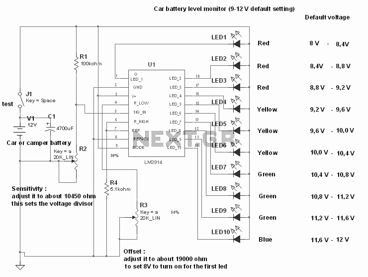
Simple but reliable car battery tester
A simple yet reliable car battery tester circuit diagram. This circuit utilizes the popular and easily accessible LM3914 integrated circuit (IC). The LM3914 is straightforward to operate, does not require external voltage regulators due to its built-in voltage regulator, and...