


Revolution Meter
#revolution meter
#strobe synchronization
#rpm measurement
#flashing LED
#potentiometer
#rotational speed
#stroboscope
#frequency adjustment
#harmonic lock

Description: This is a simple rev-counter which can measure up to 100,000 rpm with method of strobe synchronization. Its usage is easy. Put a marker on the shaft before measuring, light on the shaft by flashing LED and adjust flashing frequency with the potentiometer as keeping the marker still. The rotation will able to be read from scale of the dial. To avoid measurement error due to unintentional second or more harmonic lock, it should scan from higher value to lower value.
The rev-counter described operates on the principle of strobe synchronization, a technique that allows for accurate measurement of rotational speed by visually freezing the motion of a rotating object. The system consists of several key components: a light source, typically an LED, a frequency adjustment mechanism (potentiometer), and a dial for displaying the measured RPM.
To set up the rev-counter, a marker is placed on the rotating shaft. The LED emits light that flashes at a frequency adjustable via the potentiometer. As the frequency of the LED's flashing is varied, it is synchronized with the rotation of the shaft. When the flashing frequency matches the rotational speed of the shaft, the marker appears stationary to the observer, indicating the exact RPM.
The design must account for potential measurement errors, particularly those arising from harmonic locking. This occurs when the system inadvertently synchronizes with a harmonic of the fundamental frequency, leading to inaccurate readings. To mitigate this issue, the device is designed to scan from a higher RPM value to a lower RPM value, ensuring that the correct fundamental frequency is detected first.
The circuit would typically include a microcontroller or frequency counter to process the signals from the LED and the shaft marker. The microcontroller can be programmed to interpret the frequency of the LED flashes and convert this into a readable RPM value displayed on a dial or digital display. Additionally, filtering circuits may be implemented to eliminate noise and enhance the accuracy of the measurements.
In summary, the rev-counter is a precise instrument for measuring high rotational speeds through strobe synchronization, providing an intuitive user interface and a robust design to minimize measurement errors.This is a simple rev-counter which can measure up to 100,000 rpm with method of strobe synchronization. Its usage is easy. Put a marker on the shaft before measureing, light on the shaft by flashing LED and adjust flashing frequency with the potentiometer as keeping the marker still.
The rotation will able to be read from scale of the dial. To avoid measurment error due to unintentional second or more harmonic lock, it should scan from higher value to lower value.
The rev-counter described operates on the principle of strobe synchronization, a technique that allows for accurate measurement of rotational speed by visually freezing the motion of a rotating object. The system consists of several key components: a light source, typically an LED, a frequency adjustment mechanism (potentiometer), and a dial for displaying the measured RPM.
To set up the rev-counter, a marker is placed on the rotating shaft. The LED emits light that flashes at a frequency adjustable via the potentiometer. As the frequency of the LED's flashing is varied, it is synchronized with the rotation of the shaft. When the flashing frequency matches the rotational speed of the shaft, the marker appears stationary to the observer, indicating the exact RPM.
The design must account for potential measurement errors, particularly those arising from harmonic locking. This occurs when the system inadvertently synchronizes with a harmonic of the fundamental frequency, leading to inaccurate readings. To mitigate this issue, the device is designed to scan from a higher RPM value to a lower RPM value, ensuring that the correct fundamental frequency is detected first.
The circuit would typically include a microcontroller or frequency counter to process the signals from the LED and the shaft marker. The microcontroller can be programmed to interpret the frequency of the LED flashes and convert this into a readable RPM value displayed on a dial or digital display. Additionally, filtering circuits may be implemented to eliminate noise and enhance the accuracy of the measurements.
In summary, the rev-counter is a precise instrument for measuring high rotational speeds through strobe synchronization, providing an intuitive user interface and a robust design to minimize measurement errors.This is a simple rev-counter which can measure up to 100,000 rpm with method of strobe synchronization. Its usage is easy. Put a marker on the shaft before measureing, light on the shaft by flashing LED and adjust flashing frequency with the potentiometer as keeping the marker still.
The rotation will able to be read from scale of the dial. To avoid measurment error due to unintentional second or more harmonic lock, it should scan from higher value to lower value.

Triple Stroboscope Circuit
This circuit allows for the observation of movement between various stroboscopes. The generation of a rectangular signal is accomplished using an NE555 timer. It operates on a low power supply, which is created using a simple transformer (TR1), a traditional...
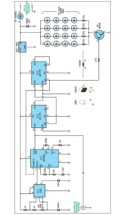
stroboscope uses white leds
This stroboscope circuit utilizes 16 high-brightness white LEDs housed within a torch structure. It also offers a signal output to a frequency counter to indicate revolutions per minute (RPM).
The stroboscope circuit is designed to provide visual indication of rotating objects...

Trigger circuits for stroboscopes
This page provides information on circuits that can trigger stroboscopes from external circuits. The circuits are designed to be integrated into stroboscope systems, allowing them to be activated using an external trigger pulse. The standard trigger pulse utilized in professional...
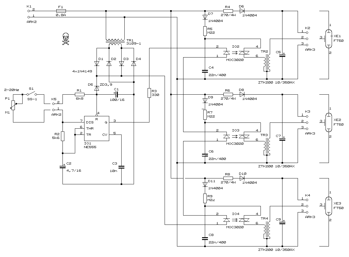
Triple Stroboscope circuit
This circuit allows for the observation of movement between various stroboscopes. The generation of a rectangular signal is accomplished using an NE555 timer. The circuit operates with a low power supply, which is constructed from a simple transformer (TR1), a...

12V stroboscope
This is one of my stroboscope designs. Usually many stoboscope circuit work directly from mains voltage, but this circuit uses 12V DC instead of mains AC. This is very good idea if you don't want to mess with direct mains...

Stroboscope Uses White LEDs
This stroboscope circuit employs 16 high-brightness white LEDs housed in a torch and provides a signal output to a frequency counter for rev counter display. The circuit utilizes IC1, a 555 astable multivibrator, which generates a signal for IC2, a...

12v stroboscope 250 400v dc circuit
The stroboscope tube requires approximately 250-400V DC for operation. This high voltage is generated by a simple voltage step-up circuit constructed from transistors Q1, Q2, and transformer T1. This circuit outputs about 230V AC, which is then rectified by diode...

music circuit
This circuit allows for the adjustment of resistance using a potentiometer and the adjustment of capacitance by opening or closing switches. By manipulating the configuration of these switches, various combinations can be achieved to obtain different effective capacitance values. It...

Using tap potentiometer loudness circuit
Figure 1.88 illustrates the loudness control circuit utilizing multiple taps on a potentiometer. In Figure (A), the connection is made between the tap and the potentiometer's input, along with the ground. An RC compensation network is employed, where the slide...