


Scope-extender
#scope-extender
#signal adapter
#low-frequency
#high-frequency
#DG201A
#chop mode
#alternate mode
#switching
#measurement

Description: The adapter enables the simultaneous display of four inputs on a single trace oscilloscope. For low-frequency signals, specifically those below 500 Hz, the adapter operates in chop mode at a frequency of 50 kHz. Although the clock can be set to run at higher speeds, the presence of switching glitches and the inherent switching time limitations of the DG201A restrict the maximum frequency to 200 kHz. For high-frequency signals, the alternate mode is recommended, utilizing a clock frequency of 200 Hz. When the clock frequency falls below 100 Hz, trace flicker becomes noticeable and undesirable. One of the four inputs is designated for triggering the horizontal trace of the oscilloscope.
The described adapter serves as a versatile tool for signal analysis, particularly in environments where multiple low-frequency and high-frequency signals need to be assessed concurrently. The operational modes—chop and alternate—provide flexibility in signal representation, allowing users to choose the most effective method based on the frequency characteristics of the inputs being analyzed.
In chop mode, the adapter samples the four inputs in rapid succession, effectively creating a composite view on the oscilloscope. This is particularly advantageous for low-frequency signals, as it allows for a clear representation without the need for excessive delay times that could obscure signal integrity. The choice of a 50 kHz clock frequency ensures that the sampling rate is sufficiently high to capture the essential features of signals below 500 Hz while avoiding significant aliasing.
For high-frequency signals, the alternate mode becomes essential. This mode alternates between the four inputs, providing a clearer view of rapidly changing signals. The use of a 200 Hz clock frequency in this mode allows for adequate refresh rates to maintain visibility of the signals without introducing excessive flicker. However, it is critical to monitor the clock frequency; if it drops below 100 Hz, the oscilloscope display may become unstable, leading to difficulties in signal interpretation.
The designated input for triggering the horizontal trace is also a vital feature. This input allows for synchronization of the oscilloscope’s horizontal sweep with one of the signals, ensuring that the displayed waveforms are aligned correctly for analysis. This functionality enhances the overall usability of the adapter, making it an essential component for engineers and technicians working with complex signal environments.
In summary, the adapter's capability to handle multiple input signals simultaneously, coupled with its operational modes tailored for different frequency ranges, provides a robust solution for efficient signal analysis in electronic applications.The adapter allows four inputs to be displayed simultaoeously on a single trace scope. For low-frequency signals, less than 500Hz, the adapter is used in the chop mode at a frequency of 50 kHz. The clock can be run faster, but switching glitches and the actual switching time of the DG201A limit the maximum frequency to 200 kHz.
High frequencies are best viewed in the alternate mode, with a clock frequency of 200 Hz. When the clock is below 100 Hz, trace flicker becomes objectionable. One of the four inputs is used to trigger the horizontal trace of the scope.
The described adapter serves as a versatile tool for signal analysis, particularly in environments where multiple low-frequency and high-frequency signals need to be assessed concurrently. The operational modes—chop and alternate—provide flexibility in signal representation, allowing users to choose the most effective method based on the frequency characteristics of the inputs being analyzed.
In chop mode, the adapter samples the four inputs in rapid succession, effectively creating a composite view on the oscilloscope. This is particularly advantageous for low-frequency signals, as it allows for a clear representation without the need for excessive delay times that could obscure signal integrity. The choice of a 50 kHz clock frequency ensures that the sampling rate is sufficiently high to capture the essential features of signals below 500 Hz while avoiding significant aliasing.
For high-frequency signals, the alternate mode becomes essential. This mode alternates between the four inputs, providing a clearer view of rapidly changing signals. The use of a 200 Hz clock frequency in this mode allows for adequate refresh rates to maintain visibility of the signals without introducing excessive flicker. However, it is critical to monitor the clock frequency; if it drops below 100 Hz, the oscilloscope display may become unstable, leading to difficulties in signal interpretation.
The designated input for triggering the horizontal trace is also a vital feature. This input allows for synchronization of the oscilloscope’s horizontal sweep with one of the signals, ensuring that the displayed waveforms are aligned correctly for analysis. This functionality enhances the overall usability of the adapter, making it an essential component for engineers and technicians working with complex signal environments.
In summary, the adapter's capability to handle multiple input signals simultaneously, coupled with its operational modes tailored for different frequency ranges, provides a robust solution for efficient signal analysis in electronic applications.The adapter allows four inputs to be displayed simultaoeously on a single trace scope. For low-frequency signals, less than 500Hz, the adapter is used in the chop mode at a frequency of 50 kHz. The clock can be run faster, but switching glitches and the actual switching time of the DG201A limit the maximum frequency to 200 kHz.
High frequencies are best viewed in the alternate mode, with a clock frequency of 200 Hz. When the clock is below 100 Hz, trace flicker becomes objectionable. One of the four inputs is used to trigger the horizontal trace of the scope.

Simple high-frequency signal generator circuit diagram
This is a simple high-frequency signal generator. By changing the inductance of the LC resonant circuit using the band switch S1, the high-frequency oscillation frequency range can be altered. The generator is divided into four frequency stages: the first stage...

Low-frequency-converter
The signals below 550 kHz include maritime mobile, distress signals, radio beacons, aircraft weather information, European Longwave-AM broadcasts, and point-to-point communications. A low-frequency converter transforms the 10 to 500 kHz LW range into a 1010 to 1550 kHz MW range...

13.8V 40A Switching Power Supply By LM3524 and LM324 PCB
This article was originally published in a slightly modified form in the QST magazine, December 1998 and January 1999, and in the Radio Amateur's Handbook, 1999. Visit the American Radio Relay League for information on these publications and a world...

Switching Improves Regulator Efficiency
In this circuit, a full-wave bridge is switched to a full-wave center tap to reduce regulator dissipation. SCR D6 switches between configurations. When D6 is off, the circuit is an FWCT rectifier using D1, D2, and D5. It applies 17...
RealView 2.0
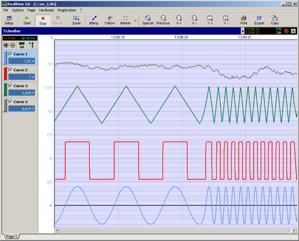
RealView is a measurement application, which records and plots measured values from analogue hardware devices in real-time. Several curves can be plotted into a single diagram. Several diagrams can be arranged on one or more pages if necessary. Plot options...

Wide-band high-frequency electric field strength meter schematic
This is a simple and low-cost broadband high-frequency electric field strength meter. The field strength of the radio signal is converted into a DC measurement for analysis. The signal is captured by a coil and processed through a diode (D1)....

Low-Frequency Prescaler
For multiplying frequencies in the 1 to 150 Hz range, this circuit utilizes a 4046B phase-locked loop (PLL) and a 100 prescaler. The output from the voltage-controlled oscillator (VCO) is phase-locked to the low-frequency input. This configuration facilitates the use...

Low-frequency-transmitter
The crystal oscillator utilizes two sections of IC1, a 4001 quad 2-input NOR gate, representing a standard and reliable design. The oscillator generates a 1.85-MHz square-wave output that feeds into IC2, a 4017 divide-by-10 counter. The count enable and reset...

High-performance power supply LM334
The circuit functions as a switching power supply designed to operate alongside a linear regulated power supply. Key characteristics include high efficiency and low dropout voltage. It effectively filters out high-frequency ripple voltage and manages instantaneous voltage variations, making it...