


Simple high-frequency signal generator circuit diagram

Description: This is a simple high-frequency signal generator. By changing the inductance of the LC resonant circuit using the band switch S1, the high-frequency oscillation frequency range can be altered. The generator is divided into four frequency stages: the first stage operates from 0.4 to 2 MHz; the second stage covers 2 to 10 MHz; the third stage ranges from 9 to 45 MHz; and the fourth stage spans 60 to 110 MHz. For component selection, transistors VT1 and VT2 should be NPN silicon types with a transition frequency (fT) of 800 MHz, such as the 9018 or C535 models. All resistors used should be 1/8W carbon film types. Capacitor C5 can be a monolithic or ceramic capacitor. Inductors L2, L3, L4, and L5 are high-frequency magnetic inductors, which may also be custom wound. Inductor L1 should be constructed with 0.6 mm high-strength wire, wound tightly in a flat coil of 8 turns, with a diameter of 7 mm. The switch S1 is a four-throw switch used to select the frequency band.
The circuit operates by utilizing an LC resonant circuit, where the inductor and capacitor values determine the oscillation frequency. The selection of the inductance through the S1 switch allows for the adjustment of the resonant frequency, enabling the generator to produce a wide range of high-frequency signals. The frequency stages are designed to cover different ranges, facilitating applications that require specific frequency outputs.
The choice of transistors VT1 and VT2 is crucial, as they must be capable of handling high frequencies with minimal distortion. The recommended transistors, such as the 9018 and C535, are well-suited for this application due to their high transition frequencies. Using 1/8W carbon film resistors ensures that the circuit maintains stability and reliability under various operating conditions.
Capacitor C5 plays a vital role in the resonant circuit, and its selection between monolithic and ceramic types allows for flexibility in component sourcing while maintaining performance. The high-frequency inductors L2, L3, L4, and L5 can be purchased or custom wound to meet specific requirements, ensuring that the generator can be tailored for various applications.
Inductor L1's construction method is essential for achieving the desired inductance and performance. The use of high-strength wire and a specific winding technique aids in minimizing losses and enhancing the quality factor of the inductor. The four-throw switch S1 enables easy selection between frequency bands, providing the user with a straightforward method to access different frequency ranges quickly.
Overall, this high-frequency signal generator is a versatile tool for generating various frequencies, suitable for testing and development in RF applications. The careful selection of components and thoughtful design ensures that it can meet the demands of high-frequency signal generation effectively. As shown for the simple high-frequency signal generator. Change the LC resonant circuit inductance with the band switch Sl, you can change the high-frequency oscillation freque ncy range. The machine can be divided into four stages:The first stage is 0.4 ~ 2MHz; The second stage is 2 ~ 10MHz; The third stage is 9 ~ 45MNz; The fourth stage is 60 ~ 110MHz. Component selection: VTl, VT2 selection fT 800MHz, 100 the NPN silicon tube, such as 9018, C535 and so on.
All with the resistance 1/8W carbon film resistors. Capacitor C5 with monolithic capacitors, ceramic capacitors can be used other. L2, L3, L4, L5 high-frequency magnetic inductors, but also their own wound. Ll with µ0.6mm high-strength wire, tightly wound flat 8 turns, bodiless wound µ7mm diameter coil. Sl pole four-throw switch with band.
The circuit operates by utilizing an LC resonant circuit, where the inductor and capacitor values determine the oscillation frequency. The selection of the inductance through the S1 switch allows for the adjustment of the resonant frequency, enabling the generator to produce a wide range of high-frequency signals. The frequency stages are designed to cover different ranges, facilitating applications that require specific frequency outputs.
The choice of transistors VT1 and VT2 is crucial, as they must be capable of handling high frequencies with minimal distortion. The recommended transistors, such as the 9018 and C535, are well-suited for this application due to their high transition frequencies. Using 1/8W carbon film resistors ensures that the circuit maintains stability and reliability under various operating conditions.
Capacitor C5 plays a vital role in the resonant circuit, and its selection between monolithic and ceramic types allows for flexibility in component sourcing while maintaining performance. The high-frequency inductors L2, L3, L4, and L5 can be purchased or custom wound to meet specific requirements, ensuring that the generator can be tailored for various applications.
Inductor L1's construction method is essential for achieving the desired inductance and performance. The use of high-strength wire and a specific winding technique aids in minimizing losses and enhancing the quality factor of the inductor. The four-throw switch S1 enables easy selection between frequency bands, providing the user with a straightforward method to access different frequency ranges quickly.
Overall, this high-frequency signal generator is a versatile tool for generating various frequencies, suitable for testing and development in RF applications. The careful selection of components and thoughtful design ensures that it can meet the demands of high-frequency signal generation effectively. As shown for the simple high-frequency signal generator. Change the LC resonant circuit inductance with the band switch Sl, you can change the high-frequency oscillation freque ncy range. The machine can be divided into four stages:The first stage is 0.4 ~ 2MHz; The second stage is 2 ~ 10MHz; The third stage is 9 ~ 45MNz; The fourth stage is 60 ~ 110MHz. Component selection: VTl, VT2 selection fT 800MHz, 100 the NPN silicon tube, such as 9018, C535 and so on.
All with the resistance 1/8W carbon film resistors. Capacitor C5 with monolithic capacitors, ceramic capacitors can be used other. L2, L3, L4, L5 high-frequency magnetic inductors, but also their own wound. Ll with µ0.6mm high-strength wire, tightly wound flat 8 turns, bodiless wound µ7mm diameter coil. Sl pole four-throw switch with band.

175MHz high-frequency amplifier circuit composed by a field effect transistor
A 175 MHz high-frequency amplifier circuit utilizing a field-effect transistor (FET) is presented. The field-effect transistor used is the 3D04H, along with its associated components and parameters.
The 175 MHz high-frequency amplifier circuit is designed to amplify signals in the specified...

High-frequency signal output amplifier
A high-frequency signal is displayed in the output amplifier. The circuit consists of a VI3 common collector amplifier (emitter follower) designed to enhance the child-band. It is a high-frequency amplifier (1-250 MHz) that increases the output voltage and boosts the...

RF Signal Generator circuit
This signal generator is designed for the realignment of radio receivers. The unit is inexpensive and relatively simple but adequately serves its intended purpose. However, the output is not a pure sine wave, which may make it unsuitable for more...
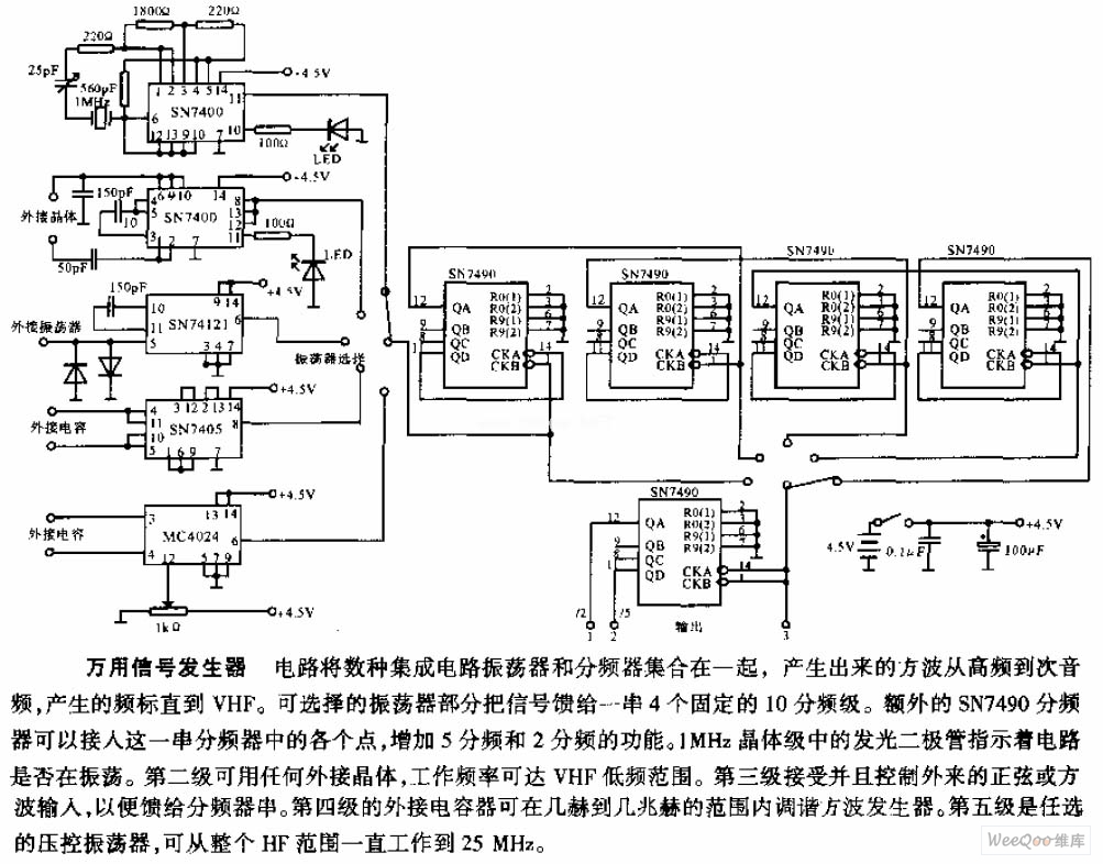
The Multi-purpose signal generator circuit
The multi-purpose signal generator circuit consists of integrated circuit oscillators and frequency dividers. It generates square waves ranging from high frequencies to sub-audio frequencies and also produces a frequency standard in the VHF range. The alternative oscillator section feeds the...

Mini Audio Signal Generator
A small audio test generator is highly effective for quickly tracing signals through audio equipment. Its primary function emphasizes speed over precision. Typically, a single sine-wave signal of approximately 1 kHz suffices, and distortion levels are not critically important. However,...

Variety of signal generator circuit
The audio function generator integrated circuit ICL8038 is capable of producing square waves, triangle waves, and sine waves. The electrical resistance and potentiometer RP1 are utilized to determine the 8-pin DC potential Ua, which is typically set to 2Ucr/3. A...

Wideband high-frequency amplifier
A wideband high-frequency amplifier circuit is presented, utilizing resistance and capacitance coupling in a common emitter configuration to amplify high-frequency signals. When a high-frequency signal with an input impedance of 50 ohms is applied to the amplifier through a coupling...

High-Frequency Oscillators
High frequencies are defined as those above 50,000 cycles per second. For industrial power supplies, the Golpitts circuit or the coupled-grid self-excited oscillator circuit is most commonly used. In either circuit, the alternating supply voltage is stepped up through a...

Signal Generator circuit
The output level was set to 3.8V peak to peak. The initial objective was to compare several different operational amplifiers (op-amps) before further optimizing the circuit. The op-amps evaluated were the TL072, LM4562, and OPA2134. The distortion spectra are presented...