


Solid laser range finder receive circuit diagram
#laser range finder
#amplifier
#current feedback
#impedance matching
#noise reduction
#signal processing
#high bandwidth
#T1 T2 coupling
#negative feedback
#output impedance

Description: This circuitry provides a magnification of 1,200,000 times, with a bandwidth ranging from 0.5 to 14 MHz. The input impedance is 700 ohms, while the output impedance is 35 ohms when measured at 5 MHz. The output noise level ranges from 0.6 to 0.8 V. In the schematic, T1 and T2 function as directly coupled amplifiers, utilizing negative current feedback through parallel connections. The enhancement of T2's emitter leads to...
This circuit is designed to achieve high levels of magnification while maintaining a broad frequency response, making it suitable for applications requiring precise signal amplification. The input impedance of 700 ohms allows for effective interfacing with various signal sources, ensuring minimal signal loss during the amplification process. The output impedance of 35 ohms at 5 MHz is optimized for compatibility with standard measurement equipment, facilitating accurate signal analysis.
The use of transistors T1 and T2 as direct coupling amplifiers is crucial for maintaining signal integrity across the amplification stages. Direct coupling minimizes phase shifts and frequency response variations that can occur with capacitive coupling. The implementation of negative current feedback in parallel configuration enhances the linearity and stability of the amplification process, reducing distortion and improving overall performance.
The circuit's bandwidth of 0.5 to 14 MHz indicates its versatility in handling a wide range of signal frequencies, making it applicable in various electronic measurement and testing scenarios. The noise level output of 0.6 to 0.8 V is indicative of the circuit's design efficiency, ensuring that the amplified signal remains distinguishable above the noise floor.
In summary, this circuit represents a sophisticated approach to high-gain signal amplification, characterized by its high magnification factor, broad bandwidth, and carefully designed impedance matching, making it suitable for advanced electronic applications.This circuitry zooms in magnification of 1200000 times, the bandwidth is 0.5~14 Mhzs, the input impedance is 700 ?, the output impedance is 35 ?(to measure in the 5 MHZ), the output level of noise is 0.6~0.8 V. In the chart, T1 and T2 are direct coupling amplifiers, and be current negative feedback in parallel connection.
The promotion of T2`s emitter l..
This circuit is designed to achieve high levels of magnification while maintaining a broad frequency response, making it suitable for applications requiring precise signal amplification. The input impedance of 700 ohms allows for effective interfacing with various signal sources, ensuring minimal signal loss during the amplification process. The output impedance of 35 ohms at 5 MHz is optimized for compatibility with standard measurement equipment, facilitating accurate signal analysis.
The use of transistors T1 and T2 as direct coupling amplifiers is crucial for maintaining signal integrity across the amplification stages. Direct coupling minimizes phase shifts and frequency response variations that can occur with capacitive coupling. The implementation of negative current feedback in parallel configuration enhances the linearity and stability of the amplification process, reducing distortion and improving overall performance.
The circuit's bandwidth of 0.5 to 14 MHz indicates its versatility in handling a wide range of signal frequencies, making it applicable in various electronic measurement and testing scenarios. The noise level output of 0.6 to 0.8 V is indicative of the circuit's design efficiency, ensuring that the amplified signal remains distinguishable above the noise floor.
In summary, this circuit represents a sophisticated approach to high-gain signal amplification, characterized by its high magnification factor, broad bandwidth, and carefully designed impedance matching, making it suitable for advanced electronic applications.This circuitry zooms in magnification of 1200000 times, the bandwidth is 0.5~14 Mhzs, the input impedance is 700 ?, the output impedance is 35 ?(to measure in the 5 MHZ), the output level of noise is 0.6~0.8 V. In the chart, T1 and T2 are direct coupling amplifiers, and be current negative feedback in parallel connection.
The promotion of T2`s emitter l..

Stereo audio power amplifier circuit using TDA2822
Circuit stereo TDA2822 audio power amplifier circuit schematics. In this series, the TDA2822M IC is utilized as the primary amplifier. Additionally, alternatives such as KA2209 and NJM2073 can also be employed.
The TDA2822 audio power amplifier circuit is designed to provide...

Amplifier Compressor MC3340P
The output is rectified, and TR2 controls the gain of the ICL. This audio compressor circuit uses an MC3340P as a variable gain amplifier.
The audio compressor circuit described utilizes an MC3340P integrated circuit, which functions as a variable gain amplifier...
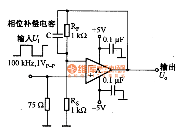
Feedback resistance circuit diagram of current feedback operational amplifier
The current feedback operational amplifier maintains a consistent bandwidth even when the open-loop gain is altered. This characteristic makes it particularly suitable for applications in video signal amplification and the driving circuits of video cables. The accompanying diagram illustrates a...

KA9270 Audio Filter Introduction
KGA8010 is a broadband distributed amplifier utilizing 0.1 um-gate GaAs P-HEMT and coplanar waveguide technologies. The KGA8010 can serve as a multi-purpose amplifier for 40 Gb/s optical communication and millimeter wave applications. Manufactured by Oki Semiconductor.
The KGA8010 broadband distributed amplifier...

DC-Coupled Audio Amplifier circuit
Designs for audio amplifiers with DC coupling to the load are not frequently seen today, despite offering distinct advantages.
Audio amplifiers that employ DC coupling to the load provide several benefits that can enhance performance in specific applications. In traditional audio...
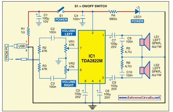
USB Powered Audio Power Amplifier
This circuit of multimedia speakers for PCs features a single-chip design, operates on a low-voltage power supply, is compatible with USB power, and allows for easy heat dissipation.
The multimedia speaker circuit is designed to enhance audio output for personal computers,...

Solid laser range finder reception circuit
The amplification of this circuit is approximately 12,000 times, with a bandwidth ranging from 0.5 to 14 MHz. The input resistance is 700 ohms, while the output resistance is 35 ohms (measured at 5 MHz). The output noise level is...

A simple and effective short-wave antenna amplifier circuit
This amplifier is designed for outdoor installation and is connected to an indoor power line box. It utilizes either 50-ohm or 75-ohm coaxial cables for the connection between indoor and outdoor units. The amplifier circuit board is depicted in Figures...
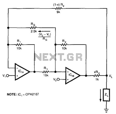
Bootstrapped Amp Current Source
This circuit responds to the difference between Vj and V2. Rq sets the gain. Resistors XR2 and (1 - X) R2 produce the bootstrap effect. These two resistors convert the circuit's output voltage to a current. IC1 and IC2 are...