


The luminous flux test circuit with optical resistors
#optical resistor
#bridge circuit
#luminous flux
#sensitivity adjustment
#voltage measurement
#thyristor
#sensor circuit
#light measurement
#electronics testing

Description: This is a luminous flux test circuit that utilizes optical resistors. In the circuit, the optical resistor RG forms a bridge with resistors RP1, RP2, R1, and R2. RP1 is employed to balance the bridge, while RP2 is used to adjust the circuit's sensitivity. When RP1 is adjusted to equalize the voltages at points a and c, the voltages VT1 and VT2 become zero, resulting in the thyristor in VSI being turned off.
The luminous flux test circuit is designed to measure light intensity using a configuration of optical resistors, which change their resistance based on the amount of light exposure. The core of this circuit is a Wheatstone bridge formed by RG, RP1, RP2, R1, and R2. The optical resistor RG responds to light levels, altering the resistance and thus influencing the balance of the bridge.
Resistor RP1 serves a critical role in fine-tuning the bridge balance. By adjusting RP1, the user can achieve equal voltage levels at nodes a and c, which is essential for accurate measurements. The second variable resistor, RP2, is responsible for adjusting the sensitivity of the entire circuit, allowing the user to calibrate the response to varying light conditions.
When the circuit is balanced—meaning the voltages at points a and c are equal—the output voltages VT1 and VT2 drop to zero. This condition indicates that the thyristor in the VSI section of the circuit is no longer conducting, effectively turning it off. The design ensures that the circuit can operate effectively under different lighting conditions by providing a means to adjust both the balance and sensitivity, making it suitable for applications requiring precise luminous flux measurements.
Overall, this luminous flux test circuit exemplifies the use of optical resistors in a bridge configuration to achieve accurate light intensity readings, with adjustable parameters for fine-tuning performance.This is a luminous flux test circuit with optical resistors. In the circuit, the optical resistor RG forms a bridge with RP1,RP2,R1 and R2; RP1 is used to adjust the balance of the bridge; RP2 is used to adjust the sensitivity of the circuit. If we adjust RP1 to make the voltages on a and c are equal, then VTl and VT2 stop, and the thyristor of VSI is off.
I..
The luminous flux test circuit is designed to measure light intensity using a configuration of optical resistors, which change their resistance based on the amount of light exposure. The core of this circuit is a Wheatstone bridge formed by RG, RP1, RP2, R1, and R2. The optical resistor RG responds to light levels, altering the resistance and thus influencing the balance of the bridge.
Resistor RP1 serves a critical role in fine-tuning the bridge balance. By adjusting RP1, the user can achieve equal voltage levels at nodes a and c, which is essential for accurate measurements. The second variable resistor, RP2, is responsible for adjusting the sensitivity of the entire circuit, allowing the user to calibrate the response to varying light conditions.
When the circuit is balanced—meaning the voltages at points a and c are equal—the output voltages VT1 and VT2 drop to zero. This condition indicates that the thyristor in the VSI section of the circuit is no longer conducting, effectively turning it off. The design ensures that the circuit can operate effectively under different lighting conditions by providing a means to adjust both the balance and sensitivity, making it suitable for applications requiring precise luminous flux measurements.
Overall, this luminous flux test circuit exemplifies the use of optical resistors in a bridge configuration to achieve accurate light intensity readings, with adjustable parameters for fine-tuning performance.This is a luminous flux test circuit with optical resistors. In the circuit, the optical resistor RG forms a bridge with RP1,RP2,R1 and R2; RP1 is used to adjust the balance of the bridge; RP2 is used to adjust the sensitivity of the circuit. If we adjust RP1 to make the voltages on a and c are equal, then VTl and VT2 stop, and the thyristor of VSI is off.
I..
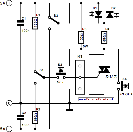
Thyristor Tester
The circuit diagram represents a useful tool for quickly testing various types of thyristors, including silicon-controlled rectifiers (SCRs) and triacs. For triacs, all four quadrants are assessed using switch S3, while testing a standard thyristor requires the adjustment of a...

Thyristor controlled forward start circuit
The 331 circuit depicted in the figure utilizes a two-way thyristor for controlling the start and stop functions of a motor. It operates without mechanical contacts, generating no noise or sparks, making it suitable for applications that require frequent operation.
The...
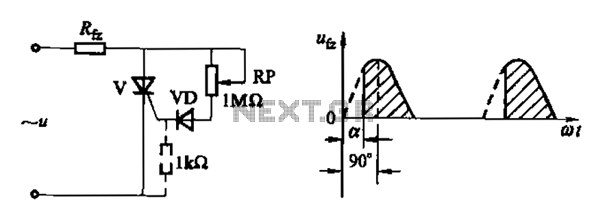
Variable resistive phase-shift trigger circuit ab
Figure 16-3 (a) illustrates a one-way thyristor, while Figure 16-3 (c) depicts a triac. The circuit characteristics indicate a simple phase shift range of 90 degrees for the thyristor and 180 degrees for the triac. These components are influenced by...
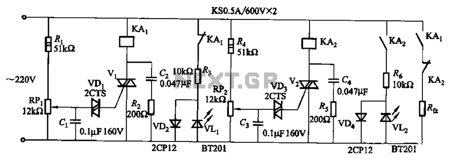
Mains undervoltage overvoltage protection circuit of five
Bidirectional thyristor control. By adjusting potentiometers RPi and RPz, the lower and upper limit values can be changed. LEDs VLi and VL2 serve as indicators for low pressure and high pressure, respectively.
The circuit utilizes a bidirectional thyristor to control the...

Car maintenance thyristor voltage regulator
An automobile permanent magnet alternator can fail, causing headlights to suddenly brighten and then go out while driving at night. The issue may stem from a damaged voltage regulator, leading to voltage spikes. This generator, a JFYJ2102 type (28V/36A) AC...

FKL-32 Operating System Circuit
The FKL-32 type automatic thyristor excitation device is designed for synchronous generators with a terminal voltage of 400V and a capacity of 500kW and below. It is used for the automatic adjustment of excitation.
The FKL-32 thyristor excitation device is an...

Positive-regulator
In the circuit, Q1 and Q2 are connected in the classic SCR or thyristor configuration. When higher input voltages or a minimal component count are required, the thyristor boost circuit can be utilized. The thyristor operates in a linear mode...

Thyristor AC automatic voltage regulator circuit diagram
The circuit utilizes a thyristor-based AC automatic voltage regulator to stabilize the brightness of lamp L. A diagonal line connects the thyristor to the T5 bridge. The trigger pulse for the thyristor is generated by a single-junction transistor, VT4. Transistors...

Coulomb meter
Another cause of voltage drift is the input current of IC1, which slowly charges capacitor C1. This effect is particularly noticeable when the output voltage is approximately 0 volts.
The circuit in question involves an integrated circuit (IC1) whose input current...