



Three-step level indicator
This circuit makes a very compact level indicator where a meter would be impractical or not justified due to cost. Resistor values will depend on type of LED us...

Ten-step voltage-level indicator
This ten-step adjustable analog level detector is capable Of sinking up to 40 milliam-peres at each output. The voltage range at the input pin should range from...

Frequency-to-volt age converter
This circuit converts frequency to voltage by taking the average dc value of the pulses from the 74121 monostable multivibrator. The one shot is triggered by th...
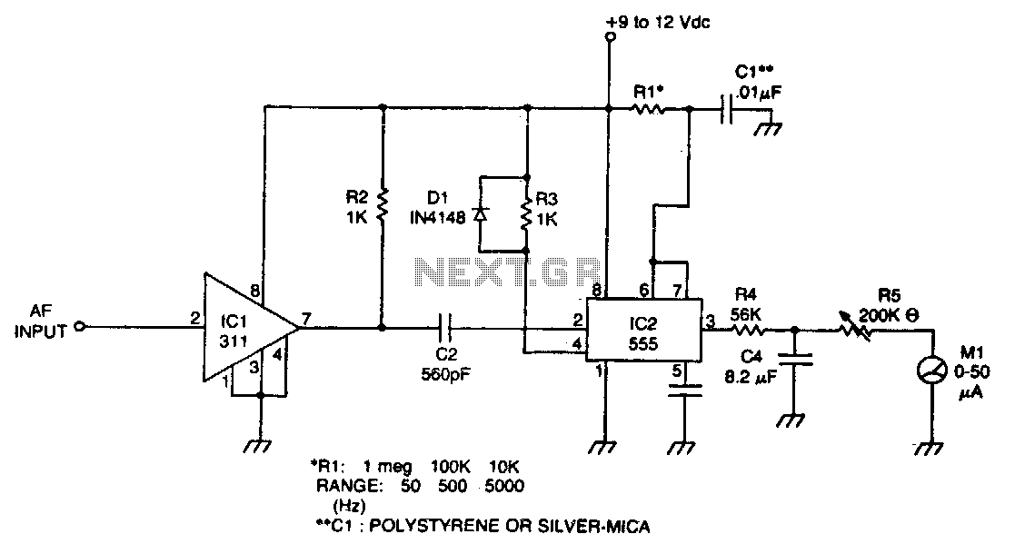
Audio frequency meter
The meter uses time averaging to produce a direct current that is proportional to the frequency...

Power-line frequency meter
The meter will indicate the frequency from a power generator. Incoming sine waves are converted to square waves by the 100K resistor and the 6,8 V zener. The sq...

Inexpensive frequency counter-tachometer
This circuit uses the low power ICM7555 (CMOS 555) to generate the gating, STORE and RESET signals. To provide the gating signal, the timer is configured as an ...

Low cost microwave field strength meter
When operating, a waveguide directs energy onto a crystal detector. The diode shown is for X-band operation. The waveguide is a 1H inch piece of plastic tubing ...

10Mhz universal counter
This is a minimum component complete Universal Counter. It can use input frequencies up to 10 MHz at INPUT A and 2 MHz at INPUT B...

True rms detector
The circuit will provide a dc output equal to the rms value of the input. Accuracy is typically 2% for a 20 Vpp input signal from 50 Hz to 100 kHz, although it"...
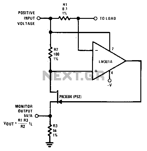
Current monitor
Rl senses current flow of a power supply...

Nano ammeter
The complete meter amplifier is a differential current-to-voltage converter with input protection, zeroing and full scale adjust provisions...

Pico ammeter
A very sensitive pico ammeter (— 1 V/pA) employs the amplifier in the inverting or current summing mode. Care must be taken to eliminate stray currents f...
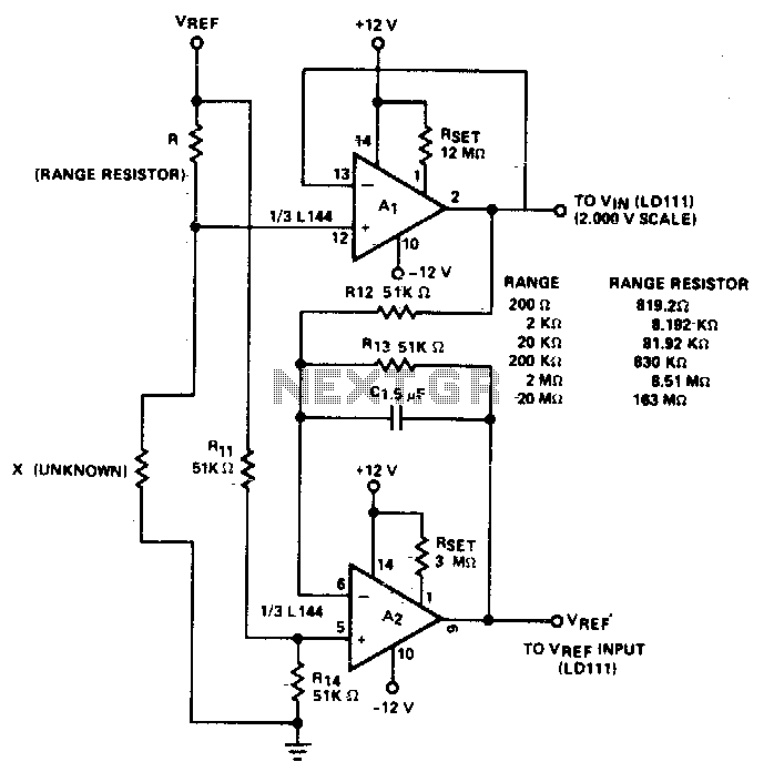
Resistance-to-voltage converter
Circuit will measure accurately to 20M when associated with a buffer amplifier (Al) having a low input bias current (IiN) < 30 nA)...

Successive approximation a-d converter
A bipolar input, high speed A/D converter uses two AM25L03s to form a 14-bit successive approximation register. The comparator is a two-stage circuit with an HA...
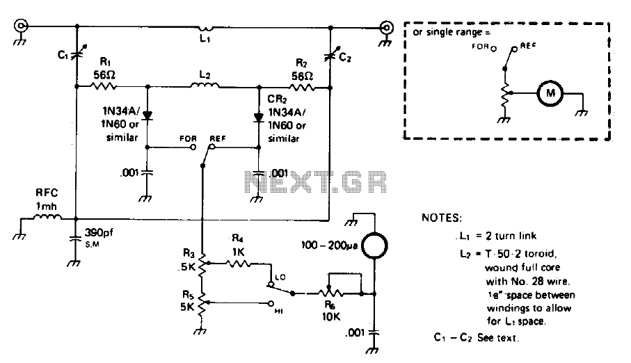
In-line wattmeter
The circuit is not frequency sensitive. Its calibration will be accurate over a wide frequency spectrum, such as the entire amateur hf spectrum, if the values o...

Centigrade thermometer 0-100c
The ultra-low bias current of the ICL7611 allows the use of large-value gain-resistors, keeping meter-current error under Yt%, and therefore saving the expense ...
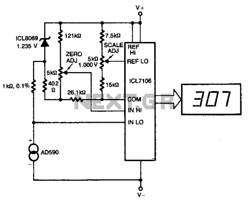
Digital thermometer with zero adjust
The ICL8069 brings the input within the common-mode range, while the 5 k ohm pots trim any offset at 218° (-55°C), and set the scale factor.
...

Digital thermocouple thermometer
This digital thermocouple thermometer uses one active component and 15 passive components. With this circuit, both type J and type thermocouples may be used. T...
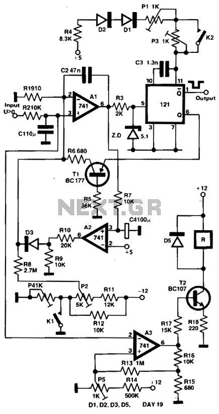
Digital temperature measuring
The output voltage of a thermocouple is converted into frequency measured by a digital frequency meter. The output thermocouple signal is proportional to the te...

Temperature sensor and DVM interface
The DVM gives a direct indication of the temperature of the sensor in degrees Centigrade. The temperature sensor IC1 gives a nominal 1 µ per degree Kelvin wh...