


Metal detector circuit with TDA0161
#TDA0161
#metal detection
#Eddy current
#LC tuned circuit
#LED indicator
#monolithic integrated circuit
#high frequency
#supply current
#coil

Description: These metal detector circuit diagram is based on the TDA0161 monolithic integrated circuit, designed for metallic body detection by detecting the variations in high frequency Eddy current losses. For detecting metals, TDA0161 require an external LC tuned circuit.
Output signal is determined by supply current changes. Independent of supply voltage, this current is high or low according to the presence or the absence of a close metallic object. This metal detector circuit use two LEDs, which offer an visual indication of presence or absence at a metals, around the coil. To adjust the circuit you need to make sure there is no metal near the coil and then set the fine adjustment to a "Mid position". After that you need to adjust the course adjustment to turn on the LED and, adjust the fine adjustment to turn off the LED. More: This detector electronic circuit operates over a wide range input voltage of 4 -35 volts. If you want you can use other values for the Cx capacitor and for L1 inductor (changing this value will affect the frequency oscillation and the detection range).
The metal detector circuit utilizing the TDA0161 integrated circuit is designed specifically for the detection of metallic objects by exploiting the principles of Eddy current loss. The TDA0161 is a monolithic IC that requires an external LC tuned circuit to function effectively. This tuned circuit is critical as it determines the operational frequency of the detector, which in turn influences the sensitivity and range of metal detection.
When a metallic object is brought close to the coil, the high-frequency oscillations generated by the LC circuit are influenced, resulting in variations in the supply current. These variations are independent of the supply voltage, allowing the circuit to maintain functionality across a wide range of input voltages, specifically from 4 to 35 volts. The output signal, which indicates the presence or absence of metal, is visually represented by two LEDs integrated into the circuit. The first LED lights up when metal is detected, while the second LED indicates when no metal is present.
For optimal performance, the circuit requires careful calibration. Initially, it is essential to ensure that no metallic objects are within proximity of the coil. The fine adjustment should be set to a mid-position, followed by the course adjustment, which is used to activate the LED. Fine-tuning is then performed to deactivate the LED, ensuring sensitivity is correctly calibrated.
The choice of components, particularly the values of the capacitor (Cx) and inductor (L1), plays a significant role in the circuit’s performance. Altering these values will directly impact the frequency oscillation characteristics and the effective detection range of the device, allowing for customization based on specific application requirements. This flexibility makes the TDA0161-based metal detector suitable for various environments and detection scenarios.These metal detector circuit diagram is based on the TDA0161 monolithic integrated circuit , designed for metallic body detection by detecting the variations in high frequency Eddy current losses. For detecting metals , TDA0161 require an external LC tuned circuit . Output signal is determined by supply current changes. Independent of supply voltage, this current is high or low according to the presence or the absence of a close metallic object.
This metal detector circuit use two LEDs , which offer an visual indication of presence or absence at a metals ,around the coil . To adjust the circuit you need to make sure there is no metal near the coil and then set the fine adjustment to a "Mid position".
After that you need to adjust the course adjustment to turn on the LED and , adjust the fine adjustment to turn off the LED. This detector electronic circuit operates over a wide range input voltage of 4 -35 volts . If you want you can use other values for the Cx capacitor and for L1 inductor ( changing this value will affect the frequency oscillation and the detection range ) .
Output signal is determined by supply current changes. Independent of supply voltage, this current is high or low according to the presence or the absence of a close metallic object. This metal detector circuit use two LEDs, which offer an visual indication of presence or absence at a metals, around the coil. To adjust the circuit you need to make sure there is no metal near the coil and then set the fine adjustment to a "Mid position". After that you need to adjust the course adjustment to turn on the LED and, adjust the fine adjustment to turn off the LED. More: This detector electronic circuit operates over a wide range input voltage of 4 -35 volts. If you want you can use other values for the Cx capacitor and for L1 inductor (changing this value will affect the frequency oscillation and the detection range).
The metal detector circuit utilizing the TDA0161 integrated circuit is designed specifically for the detection of metallic objects by exploiting the principles of Eddy current loss. The TDA0161 is a monolithic IC that requires an external LC tuned circuit to function effectively. This tuned circuit is critical as it determines the operational frequency of the detector, which in turn influences the sensitivity and range of metal detection.
When a metallic object is brought close to the coil, the high-frequency oscillations generated by the LC circuit are influenced, resulting in variations in the supply current. These variations are independent of the supply voltage, allowing the circuit to maintain functionality across a wide range of input voltages, specifically from 4 to 35 volts. The output signal, which indicates the presence or absence of metal, is visually represented by two LEDs integrated into the circuit. The first LED lights up when metal is detected, while the second LED indicates when no metal is present.
For optimal performance, the circuit requires careful calibration. Initially, it is essential to ensure that no metallic objects are within proximity of the coil. The fine adjustment should be set to a mid-position, followed by the course adjustment, which is used to activate the LED. Fine-tuning is then performed to deactivate the LED, ensuring sensitivity is correctly calibrated.
The choice of components, particularly the values of the capacitor (Cx) and inductor (L1), plays a significant role in the circuit’s performance. Altering these values will directly impact the frequency oscillation characteristics and the effective detection range of the device, allowing for customization based on specific application requirements. This flexibility makes the TDA0161-based metal detector suitable for various environments and detection scenarios.These metal detector circuit diagram is based on the TDA0161 monolithic integrated circuit , designed for metallic body detection by detecting the variations in high frequency Eddy current losses. For detecting metals , TDA0161 require an external LC tuned circuit . Output signal is determined by supply current changes. Independent of supply voltage, this current is high or low according to the presence or the absence of a close metallic object.
This metal detector circuit use two LEDs , which offer an visual indication of presence or absence at a metals ,around the coil . To adjust the circuit you need to make sure there is no metal near the coil and then set the fine adjustment to a "Mid position".
After that you need to adjust the course adjustment to turn on the LED and , adjust the fine adjustment to turn off the LED. This detector electronic circuit operates over a wide range input voltage of 4 -35 volts . If you want you can use other values for the Cx capacitor and for L1 inductor ( changing this value will affect the frequency oscillation and the detection range ) .
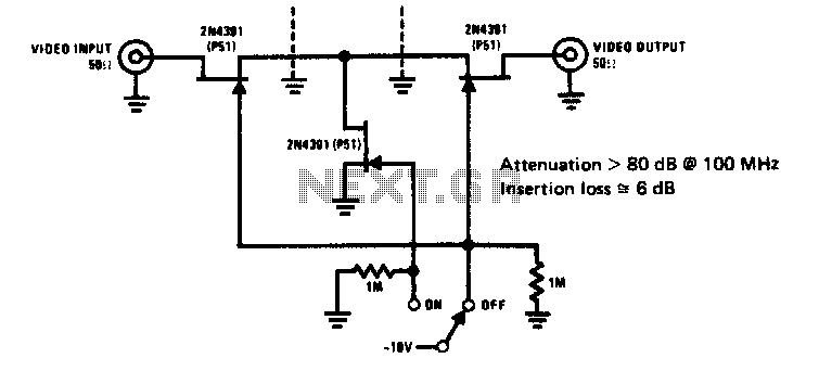
High frequency switch
The 2N4391 features a low ON resistance of 30 ohms and a high OFF impedance of less than 0 pF when in the off state. With appropriate layout and an optimal switch configuration, the stated performance can be easily attained.
The...

High Frequency Waveform GeneratorCircuit
A high-frequency waveform generator is highly beneficial for electronic experimentation and design. This circuit generates sine wave oscillations; however, it can be modified to produce triangle or square wave functions. The frequency can be controlled using current. By disconnecting the...

High Frequency Colpitts Crystal Oscillator
Op-amps have been widely used in low-frequency oscillators.
Op-amps, or operational amplifiers, are versatile components frequently utilized in the design of low-frequency oscillators. These devices are capable of generating periodic waveforms, such as sine, square, or triangular waves, which are essential...

Metal Detector Circuit
The device being constructed will serve as a metal detector, capable of locating metal objects such as coins, nails, and keys, including car keys that may be misplaced. It can also detect gold, although it may not possess industrial strength....

High Frequency Switch
This is a high-frequency switch circuit. This circuit utilizes the 2N4391 transistor. When in the off state, it provides a high off-impedance of less than 0.2 pF and exhibits a low on-resistance.
The high-frequency switch circuit designed with the 2N4391 transistor...

egan fet silicon power shoot out volume 10 high frequency resonant converters
Distributed power systems are commonly used in telecommunications, networking, and high-end server applications, utilizing a 48 V bus voltage derived from the telecom industry. This 48 V bus supplies several isolated point-of-load (POL) converters that power the end loads, with...

TDA0161 Metal Detector
This circuit features an LED indicator with two identical LEDs depicted in the schematic. The modification in Advanced Schematic-2 enhances the detector's sensitivity by incorporating a manual reset function to eliminate the built-in hysteresis of the integrated circuit (IC). Standard...

High frequency signal generator
A tapped-coil Colpitts oscillator is utilized at Q1 to deliver four tuning ranges: 1.7 to 3.131 MHz, 3.0 to 5.6 MHz, 5.0 to 12 MHz, and 11.5 to 31 MHz. A Zener diode (D2) is incorporated at Q1 to reduce...

7MHz high frequency carrier oscillator
The 2SA130 transistor is used in an oscillator circuit with an oscillation frequency of 7 MHz. The power supply voltage is 6V, and the load is a frequency-selective resonant circuit with a quality factor of 600.
The circuit utilizes the 2SA130...