


PIC16F877A Astro Clock
#PIC16F877A
#astro clock
#timers
#alarms
#rechargeable battery
#keyboard interface
#sidereal time
#Moon phase
#Julian-time

Description: It has 16 timers that can be independently paused and restarted, and can run forward or backward. There are 16 alarms with configurable sounds and actions. Timers can show Earth, Mars, Jupiter, etc. times at the same time. How about sidereal time, Moon phase, Jupiter's Great Red Spot transit time, and anything periodic in general? Simultaneous 24-hour and Julian-time decimal display. All changes in configuration can be done from the device's keyboard - no computer necessary. External AC power with built-in rechargeable battery, so you can take the clock around. High on the geekness scale. The 5V Power Supply block contains the voltage stabilizer and filtering capacitors from the power supply on the modem board. The Speaker Amplifier block is the LM386-based amplifier circuit that was on the original modem board. The speaker is the internal modem speaker. The PICkit 2 Programmer port is intended for reprogramming the microcontroller without disassembling the clock. The DB25 to 6-pin adapter (see the picture) is not shown. If your keyboard has different layout than the one shown, refer to Using Different Keyboard in the Code section. I used a Techstar 16 characters * 2 lines LCD Module with backlight. These modules are pretty standard, so almost any 16x2 LCD module will work. Backlight is a plus, but it is not mandatory.
The described electronic device is a multifunctional timer and alarm clock system that integrates a variety of features suitable for both practical and experimental applications. The device includes 16 independent timers that can be paused and restarted, allowing for versatile timing functions. The timers are capable of displaying time for various celestial bodies such as Earth, Mars, and Jupiter simultaneously, which can be particularly useful for astronomical studies or enthusiasts.
In addition to the timers, the clock features 16 configurable alarms, each capable of being set with distinct sounds and actions, enhancing its usability for reminders or notifications. The device also incorporates the ability to display sidereal time, lunar phases, and other periodic phenomena, making it a valuable tool for those interested in astronomy.
The display functionality is supported by a Techstar 16x2 LCD module, which provides clear visibility of the information being presented. The backlight feature, while not essential, adds convenience for viewing in low-light conditions. The device operates on an external AC power source, complemented by a built-in rechargeable battery, ensuring portability and continuous operation.
The power supply section of the device includes a 5V voltage stabilizer along with filtering capacitors, ensuring stable operation of the internal circuitry. An LM386-based speaker amplifier is integrated into the system, allowing for sound output through an internal modem speaker, which is essential for alarm notifications.
For programming and configuration, the device includes a PICkit 2 programmer port, facilitating microcontroller reprogramming without the need to disassemble the device. This feature enhances the flexibility of the device, allowing for updates and customizations as needed. The keyboard interface is designed to be user-friendly, with the ability to accommodate different keyboard layouts, thus broadening its accessibility to users with varying preferences.
Overall, this electronic device represents a sophisticated amalgamation of timing, astronomical display, and user-friendly programming capabilities, making it a noteworthy addition to any tech enthusiast's collection.It has 16 timers that can be independently paused and restarted, and can run forward or backward. There are 16 alarms with configurable sounds and actions. Timers can show Earth, Mars, Jupiter, etc. times at the same time. How about sidereal time, Moon phase, Jupiter's Great Red Spot transit time, and anything periodic in general? Simultaneous 24-hour and Julian-time decimal display. All changes in configuration can be done from the device's keyboard - no computer necessary. External AC power with built-in rechargeable battery, so you can take the clock around. High on the geekness scale. The 5V Power Supply block contains the voltage stabilizer and filtering capacitors from the power supply on the modem board. The Speaker Amplifier block is the LM386-based amplifier circuit that was on the original modem board.
The speaker is the internal modem speaker. The PICkit 2 Programmer port is intended for reprogramming the microcontroller without disassembling the clock. The DB25 to 6-pin adapter (see the picture) is not shown. If your keyboard has different layout than the one shown, refer to Using Different Keyboard in the Code section.
I used a Techstar 16 characters * 2 lines LCD Module with backlight. These modules are pretty standard, so almost any 16x2 LCD module will work. Backlight is a plus, but it is not mandatory.
The described electronic device is a multifunctional timer and alarm clock system that integrates a variety of features suitable for both practical and experimental applications. The device includes 16 independent timers that can be paused and restarted, allowing for versatile timing functions. The timers are capable of displaying time for various celestial bodies such as Earth, Mars, and Jupiter simultaneously, which can be particularly useful for astronomical studies or enthusiasts.
In addition to the timers, the clock features 16 configurable alarms, each capable of being set with distinct sounds and actions, enhancing its usability for reminders or notifications. The device also incorporates the ability to display sidereal time, lunar phases, and other periodic phenomena, making it a valuable tool for those interested in astronomy.
The display functionality is supported by a Techstar 16x2 LCD module, which provides clear visibility of the information being presented. The backlight feature, while not essential, adds convenience for viewing in low-light conditions. The device operates on an external AC power source, complemented by a built-in rechargeable battery, ensuring portability and continuous operation.
The power supply section of the device includes a 5V voltage stabilizer along with filtering capacitors, ensuring stable operation of the internal circuitry. An LM386-based speaker amplifier is integrated into the system, allowing for sound output through an internal modem speaker, which is essential for alarm notifications.
For programming and configuration, the device includes a PICkit 2 programmer port, facilitating microcontroller reprogramming without the need to disassemble the device. This feature enhances the flexibility of the device, allowing for updates and customizations as needed. The keyboard interface is designed to be user-friendly, with the ability to accommodate different keyboard layouts, thus broadening its accessibility to users with varying preferences.
Overall, this electronic device represents a sophisticated amalgamation of timing, astronomical display, and user-friendly programming capabilities, making it a noteworthy addition to any tech enthusiast's collection.It has 16 timers that can be independently paused and restarted, and can run forward or backward. There are 16 alarms with configurable sounds and actions. Timers can show Earth, Mars, Jupiter, etc. times at the same time. How about sidereal time, Moon phase, Jupiter's Great Red Spot transit time, and anything periodic in general? Simultaneous 24-hour and Julian-time decimal display. All changes in configuration can be done from the device's keyboard - no computer necessary. External AC power with built-in rechargeable battery, so you can take the clock around. High on the geekness scale. The 5V Power Supply block contains the voltage stabilizer and filtering capacitors from the power supply on the modem board. The Speaker Amplifier block is the LM386-based amplifier circuit that was on the original modem board.
The speaker is the internal modem speaker. The PICkit 2 Programmer port is intended for reprogramming the microcontroller without disassembling the clock. The DB25 to 6-pin adapter (see the picture) is not shown. If your keyboard has different layout than the one shown, refer to Using Different Keyboard in the Code section.
I used a Techstar 16 characters * 2 lines LCD Module with backlight. These modules are pretty standard, so almost any 16x2 LCD module will work. Backlight is a plus, but it is not mandatory.

Voltage Ampere and Temperature meter with PIC16F877A
This project was designed and constructed as enhancement to the 0-30V Stabilized Power Supply Project with the DIY electronics hobbyist in mind. The circuit uses a single PIC Microchip to perform the Voltage, Current and Temperature conversions and display functions....

Simple LED blinking using PIC16F877A
This project involves a basic LED blinking circuit utilizing the PIC16F877A microcontroller. It features two LEDs connected to the PIC16F877A, with the source code adapted from the 16F template.
The circuit design consists of the PIC16F877A microcontroller, which serves as the...

pic PIC16f877A resets due to external noise
Connect a relay with a PIC microcontroller, and whenever a load is applied to the relay contacts, the PIC16F877A resets. This issue has been partially resolved by triggering another relay from the basic relay attached to the PIC, but this...

Security Alarm System (PIC16F877A)
This system uses a Microchip's PIC16F877A as a main controller, LM339 as sensor interface, UM3561 as a tone generator and PC2002 as a speaker driver (audio amplifier). LM7805, LM7812 and LM317 voltage regulators are used to obtain +5V, +12V and...

Keyer circuit
A larger version of the circuit diagram can be accessed by clicking here. The circuit was created using Eagle from CadSoft, which is a free schematic and PCB layout software for small non-commercial projects. The core component of the keyer...
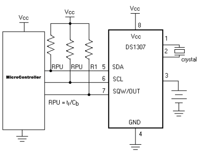
Application Project On W5100 SoftLib DS1307 SoftMax7219
This project is an application that utilizes the W5100 library for network connections, the DS1307 for time display, and the MAX7219 for controlling 7-segment displays. It features a web page that allows users to read the time and modify the...

PIC Stepper Motor Tester
Determining the identification of drive wires on a unipolar stepper motor, which is commonly found in surplus or salvaged equipment. The platform utilized is a PIC16F877A microcontroller programmed with BoostC, interfaced via RS232 to a PC running a terminal program....

Line Following Robot
Lectures on line following robots consist of multiple sessions, including Lecture 1 (a), Lecture 1 (b), and Lecture 1 (c). A concept diagram is provided for a 1 cm line following robot, along with a schematic for a robot utilizing...
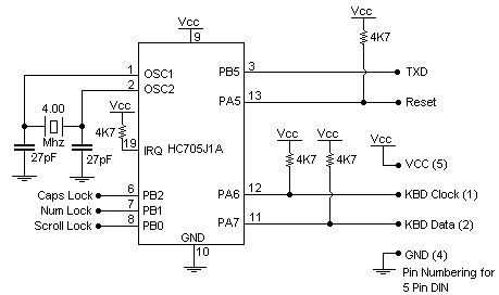
keyboard circuit
This document details the AT Keyboard Interface and AT Keyboard Protocols. It includes an example of a Keyboard to ASCII decoder utilizing a 68HC705J1A microcontroller.
The AT Keyboard Interface is a standard communication protocol used primarily in personal computers to facilitate...