


Ultrasonic range finder using 8051

Description: A simple ultrasonic range finder using the 8051 microcontroller is presented in this article. This ultrasonic rangefinder can measure distances up to 2.5 meters with an accuracy of 1 centimeter. The AT89S51 microcontroller and the ultrasonic transducer module HC-SR04 form the basis of this circuit. The ultrasonic module sends a signal to the object, then picks up its echo and outputs a waveform whose time period is proportional to the distance. The microcontroller accepts this signal, performs necessary processing, and displays the corresponding distance on a 3-digit seven-segment display. This circuit finds numerous applications in projects such as automotive parking sensors, obstacle warning systems, terrain monitoring robots, and industrial distance measurements. The HC-SR04 is an ultrasonic ranging module designed for embedded system projects like this. It has a resolution of 0.3 cm, and the ranging distance is from 2 cm to 500 cm. It operates from a 5V DC supply, and the standby current is less than 2 mA. The module transmits an ultrasonic signal, picks up its echo, measures the time elapsed between the two events, and outputs a waveform whose high time is modulated by the measured time, which is proportional to the distance. The HC-SR04 module has four pins: Vcc, Trigger, Echo, and GND.
Trigger: The trigger signal for starting the transmission is given to this pin. The trigger signal must be a pulse with a 10 µs high time. When the module receives a valid trigger signal, it issues 8 pulses of 40 kHz ultrasonic sound from the transmitter. The echo of this sound is picked up by the receiver. The next triggering pulse can be given only after the echo has faded away, and this time period is called the cycle period. The cycle period for the HC-SR04 must not be below 50 ms. According to the datasheet, the distance can be calculated from the echo pulse width using specific equations. The ultrasonic module is interfaced to the microcontroller through P3.0 and P3.1 pins. Port 0 is used for transmitting the 8-bit display data to the display, while port pins P1.0, P1.1, and P1.2 are used for transmitting display drive signals for the corresponding display units D1, D2, and D3. A push-button switch S1, capacitor C3, and resistor R9 form a de-bouncing reset circuitry. Capacitors C1, C2, and crystal X1 are associated with the clock circuit.
The schematic design of the ultrasonic range finder can be divided into several functional blocks. The first block consists of the microcontroller (AT89S51), which serves as the central processing unit. It interfaces with the HC-SR04 ultrasonic module, which includes a transmitter and receiver for ultrasonic signals. The microcontroller's P3.0 pin is connected to the Trigger pin of the HC-SR04, while the Echo pin is connected to P3.1 for receiving the echo signal.
The display section consists of a 3-digit seven-segment display driven by Port 0 of the microcontroller. Each segment of the display is activated by sending the appropriate binary data from the microcontroller, allowing for the visual representation of the distance measured by the ultrasonic sensor.
The timing and control logic is managed by the microcontroller's Timer 1, which is configured in mode 2 for auto-reload functionality. This allows for precise timing of the echo signal measurement, ensuring accurate distance calculations. The de-bouncing circuitry, consisting of S1, C3, and R9, ensures that any noise from the push-button does not interfere with the reset operation of the microcontroller.
Overall, this ultrasonic range finder circuit effectively combines the capabilities of the 8051 microcontroller and the HC-SR04 ultrasonic module to provide reliable distance measurements for various applications in embedded systems.A simple ultrasonic range finder using 8051 microcontroller is presented in this article. This ultrasonic rangefinder can measure distances up to 2. 5 meters at an accuracy of 1 centi meter. AT89s51 microcontroller and the ultrasonic transducer module HC-SR04 forms the basis of this circuit. The ultrasonic module sends a signal to the object, then picks up its echo and outputs a wave form whose time period is proportional to the distance. The microcontroller accepts this signal, performs necessary processing and displays the corresponding distance on the 3 digit seven segment display. This circuit finds a lot of application in projects like automotive parking sensors, obstacle warning systems, terrain monitoring robots, industrial distance measurements etc.
HC-SR04 is an ultrasonic ranging module designed for embedded system projects like this. It has a resolution of 0. 3cm and the ranging distance is from 2cm to 500cm. It operates from a 5V DC supply and the standby current is less than 2mA. The module transmits an ultrasonic signal, picks up its echo, measures the time elapsed between the two events and outputs a waveform whose high time is modulated by the measured time which is proportional to the distance. . The photograph of an HC-SR04 module is shown below. The supporting circuits fabricated on the module makes it almost stand alone and what the programmer need to do is to send a trigger signal to it for initiating transmission and receive the echo signal from it for distance calculation.
The HR-SR04 has four pins namely Vcc, Trigger, Echo, GND and they are explained in detail below. 2)Trigger: The trigger signal for starting the transmission is given to this pin. The trigger signal must be a pulse with 10uS high time. When the module receives a valid trigger signal it issues 8 pulses of 40KHz ultrasonic sound from the transmitter. The echo of this sound is picked by the receiver. From the timing diagram, you can see that the 40KHz pulse train is transmitted just after the 10uS triggering pulse and the echo output is obtained after some more time.
The next triggering pulse can be given only after the echo is faded away and this time period is called cycle period. The cycle period for HC-SR04 must not be below 50mS. According to datasheet, the distance can be calculated from the echo pulse width using the following equations.
The ultrasonic module is interfaced to the microcontroller through P3. 0 and P3. 1 pins. Port0 used for transmitting the 8 bit display data to the display and port pins P1. 0, P1. 1, P1. 2 are used for transmitting display drive signals for the corresponding display units D1, D2, D3. Push button switch S1, capacitor C3 and resistor R9 forms a de-bouncing reset circuitry. Capacitors C1, C2 and crystal X1 are associated with the clock circuit. ORG 00H // origin MOV DPTR, #LUT // moves the address of LUT to DPTR MOV P1, #00000000B // sets P1 as output port MOV P0, #00000000B // sets P0 as output port CLR P3. 0 // sets P3. 0 as output for sending trigger SETB P3. 1 // sets P3. 1 as input for receiving echo MOV TMOD, #00100000B // sets timer1 as mode 2 auto reload timer MAIN: MOV TL1, #207D // loads the initial value to start counting from MOV TH1, #207D // loads the reload value MOV A, #00000000B // clears accumulator SETB P3.
0 // starts the trigger pulse ACALL DELAY1 // gives 10uS width for the trigger pulse CLR P3. 0 // ends the trigger pulse HERE: JNB P3. 1, HERE // loops here until echo is received BACK: SETB TR1 // starts the timer1 HERE1: JNB TF1, HERE1 // loops here until timer overflows (ie;48 count) CLR TR1 // stops the timer CLR TF1 // clears timer flag 1 INC A // increments A for every timer1 overflow JB P3. 1, BACK // jumps to BACK if echo is still available MOV R4, A // saves the value of A to R4 ACALL DLOOP // calls the display loop SJMP MAIN // jumps to MAIN loop DELAY1: MOV R6, #2D // 10uS delay LABEL1: DJNZ R6, LABEL1 RET
Trigger: The trigger signal for starting the transmission is given to this pin. The trigger signal must be a pulse with a 10 µs high time. When the module receives a valid trigger signal, it issues 8 pulses of 40 kHz ultrasonic sound from the transmitter. The echo of this sound is picked up by the receiver. The next triggering pulse can be given only after the echo has faded away, and this time period is called the cycle period. The cycle period for the HC-SR04 must not be below 50 ms. According to the datasheet, the distance can be calculated from the echo pulse width using specific equations. The ultrasonic module is interfaced to the microcontroller through P3.0 and P3.1 pins. Port 0 is used for transmitting the 8-bit display data to the display, while port pins P1.0, P1.1, and P1.2 are used for transmitting display drive signals for the corresponding display units D1, D2, and D3. A push-button switch S1, capacitor C3, and resistor R9 form a de-bouncing reset circuitry. Capacitors C1, C2, and crystal X1 are associated with the clock circuit.
The schematic design of the ultrasonic range finder can be divided into several functional blocks. The first block consists of the microcontroller (AT89S51), which serves as the central processing unit. It interfaces with the HC-SR04 ultrasonic module, which includes a transmitter and receiver for ultrasonic signals. The microcontroller's P3.0 pin is connected to the Trigger pin of the HC-SR04, while the Echo pin is connected to P3.1 for receiving the echo signal.
The display section consists of a 3-digit seven-segment display driven by Port 0 of the microcontroller. Each segment of the display is activated by sending the appropriate binary data from the microcontroller, allowing for the visual representation of the distance measured by the ultrasonic sensor.
The timing and control logic is managed by the microcontroller's Timer 1, which is configured in mode 2 for auto-reload functionality. This allows for precise timing of the echo signal measurement, ensuring accurate distance calculations. The de-bouncing circuitry, consisting of S1, C3, and R9, ensures that any noise from the push-button does not interfere with the reset operation of the microcontroller.
Overall, this ultrasonic range finder circuit effectively combines the capabilities of the 8051 microcontroller and the HC-SR04 ultrasonic module to provide reliable distance measurements for various applications in embedded systems.A simple ultrasonic range finder using 8051 microcontroller is presented in this article. This ultrasonic rangefinder can measure distances up to 2. 5 meters at an accuracy of 1 centi meter. AT89s51 microcontroller and the ultrasonic transducer module HC-SR04 forms the basis of this circuit. The ultrasonic module sends a signal to the object, then picks up its echo and outputs a wave form whose time period is proportional to the distance. The microcontroller accepts this signal, performs necessary processing and displays the corresponding distance on the 3 digit seven segment display. This circuit finds a lot of application in projects like automotive parking sensors, obstacle warning systems, terrain monitoring robots, industrial distance measurements etc.
HC-SR04 is an ultrasonic ranging module designed for embedded system projects like this. It has a resolution of 0. 3cm and the ranging distance is from 2cm to 500cm. It operates from a 5V DC supply and the standby current is less than 2mA. The module transmits an ultrasonic signal, picks up its echo, measures the time elapsed between the two events and outputs a waveform whose high time is modulated by the measured time which is proportional to the distance. . The photograph of an HC-SR04 module is shown below. The supporting circuits fabricated on the module makes it almost stand alone and what the programmer need to do is to send a trigger signal to it for initiating transmission and receive the echo signal from it for distance calculation.
The HR-SR04 has four pins namely Vcc, Trigger, Echo, GND and they are explained in detail below. 2)Trigger: The trigger signal for starting the transmission is given to this pin. The trigger signal must be a pulse with 10uS high time. When the module receives a valid trigger signal it issues 8 pulses of 40KHz ultrasonic sound from the transmitter. The echo of this sound is picked by the receiver. From the timing diagram, you can see that the 40KHz pulse train is transmitted just after the 10uS triggering pulse and the echo output is obtained after some more time.
The next triggering pulse can be given only after the echo is faded away and this time period is called cycle period. The cycle period for HC-SR04 must not be below 50mS. According to datasheet, the distance can be calculated from the echo pulse width using the following equations.
The ultrasonic module is interfaced to the microcontroller through P3. 0 and P3. 1 pins. Port0 used for transmitting the 8 bit display data to the display and port pins P1. 0, P1. 1, P1. 2 are used for transmitting display drive signals for the corresponding display units D1, D2, D3. Push button switch S1, capacitor C3 and resistor R9 forms a de-bouncing reset circuitry. Capacitors C1, C2 and crystal X1 are associated with the clock circuit. ORG 00H // origin MOV DPTR, #LUT // moves the address of LUT to DPTR MOV P1, #00000000B // sets P1 as output port MOV P0, #00000000B // sets P0 as output port CLR P3. 0 // sets P3. 0 as output for sending trigger SETB P3. 1 // sets P3. 1 as input for receiving echo MOV TMOD, #00100000B // sets timer1 as mode 2 auto reload timer MAIN: MOV TL1, #207D // loads the initial value to start counting from MOV TH1, #207D // loads the reload value MOV A, #00000000B // clears accumulator SETB P3.
0 // starts the trigger pulse ACALL DELAY1 // gives 10uS width for the trigger pulse CLR P3. 0 // ends the trigger pulse HERE: JNB P3. 1, HERE // loops here until echo is received BACK: SETB TR1 // starts the timer1 HERE1: JNB TF1, HERE1 // loops here until timer overflows (ie;48 count) CLR TR1 // stops the timer CLR TF1 // clears timer flag 1 INC A // increments A for every timer1 overflow JB P3. 1, BACK // jumps to BACK if echo is still available MOV R4, A // saves the value of A to R4 ACALL DLOOP // calls the display loop SJMP MAIN // jumps to MAIN loop DELAY1: MOV R6, #2D // 10uS delay LABEL1: DJNZ R6, LABEL1 RET

Pots water alarm circuit
The flowers in pots require watering, as relying solely on the observation of moist soil surfaces can be unreliable. To address this issue, a flower watering indicator has been developed. This circuit includes a field effect transistor (VT1), a second...

Software delay routine in 8051 for generating different time delays
A software delay routine in the 8051 microcontroller is utilized to generate various time delays. This project features a sine wave generator circuit that employs a software delay within the 8051 architecture. The AT89C51 microcontroller serves as the core component...
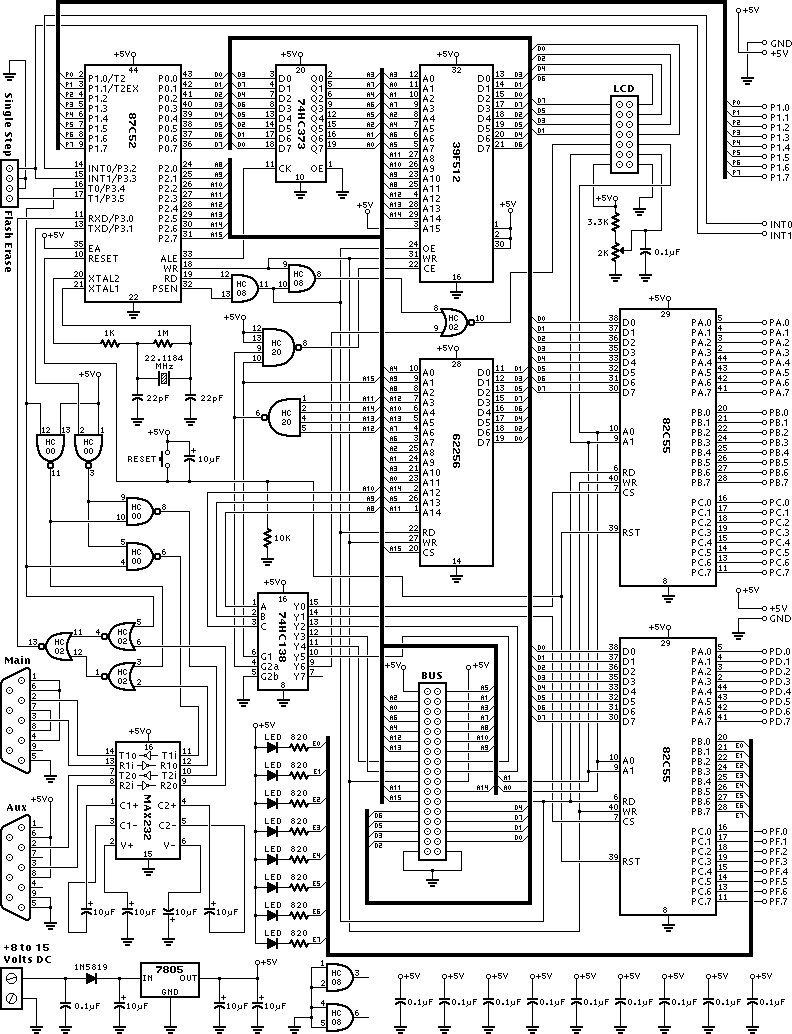
8051 Development System Circuit Board 3
This schematic is provided with the intention of being useful, but it comes without any warranty, including implied warranties of merchantability or fitness for a particular purpose. The address bus in this schematic is connected in a unique manner, optimized...

integrated circuit Improving absolute precision of ADC to balance battery voltage
Utilize a high-performance microcontroller (Piccolo TMS320F28035, 12-bit resolution, +/- 4 LSB offset, +/- 60 LSB gain) to measure the voltage across stacked battery cells and control related analog electronics for charge equalization. The microcontroller will also save data in EEPROM...
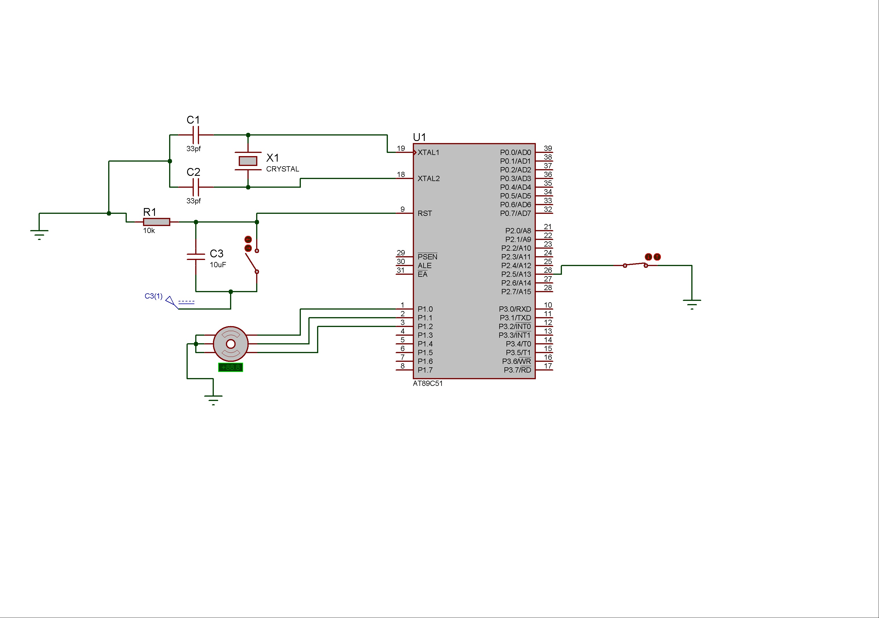
Controlling of Stepper Motor rotation in both direction using 8051 Microcontroller
Stepper motors consist of a permanent magnet rotating shaft, known as the rotor, and electromagnets on the stationary part that surrounds the motor, referred to as the stator. One complete rotation of a stepper motor is illustrated. At position 1,...

DC motor driver for DCMP(AVR-008)
A microcontroller is used to control various types of DC motors, including permanent magnet DC motors, DC servo motors, and stepper motors. This project utilizes the AVR-008 microcontroller from Circuits-Home, which is frequently referred to as the 3-in-1 driver motor...

Distance measurement system using PING Ultrasonic Range Finder
A PING Ultrasonic Range Finder is designed to create a system capable of detecting and measuring the distance (in millimeters) to the nearest object in front of the sensor. It functions similarly to a digital measuring tape; the user points...

pc based digital ic tester
Check the following ICs: 7400, 7402, 7404, 7408, 7432, 7486. A Visual Basic program is utilized to display the results on the PC. The microcontroller AT89S52 receives the IC number from the PC, verifies the logic gates with the truth...

lcd interfacing
This document provides an example of how to interface with the standard Hitachi HD44780 LCD using an 8051 microcontroller and the SDCC C compiler. A standard 16-character by 2-line LCD module is utilized, as illustrated in the schematic below. The...