


Handy Board Software
This page provides links to software and hardware designs contributed by Handy Board users. If you would like to contribute some work of your own to the Handy B...

The Handy Board
...

Interfacing to External EEPROM
An external EEPROM can be useful for several different reasons. External EEPROMs allow much more data to be stored than is available on the 18F4520. In addition...

Data logging with an EEPROM
Your task is to use the PIC to log data from an analog input on an EEPROM, and after the data collection is over, to send the data back from the EEPROM to a PC ...

Programming the XMEGA with an ISP
Atmel`s XMEGA series of microcontrollers are neat little pieces of hardware; with a very fast clock, a ton of IO, USB, and up to 8 UART ports, these neat little...
AVR Programming The Hardware
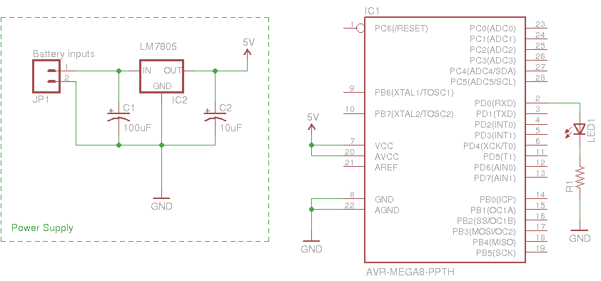
You may be able to write the most eloquent code in the history of embedded systems but without a way to run it on the hardware it will be worthless.....

Super simple serial terminal
This hack shows how to make a dumb terminal out of a keyboard, LCD screen, and an 8-bit microcontroller. From time to time, a portable dumb terminal can be hand...

microprocessor based frequency counter
In order to make the circuit work, it is important to set the fuse bits inside the AVR micro controller correctly. Theses fuse bits can be set with the programm...

Learning RC5 decoder PIC16f628a
...

MidiMotor2 Module
The logic power and CAN signals come in from N4 pins 3 through 8. The CAN signals are connected to the MCP2551 CAN physical layer IC, U5. The transmit and recei...

IO8 Module
The bus is connected to the 2G—5 shrouded conenctor N9. The two CAN bus signals are fed into the PCP2551 CAN bus transceiver U2. The output of U2 is fed to th...

Layout Control Mother Board
The purpose of the layout control mother board is to provide a simple way to allow people to control portions of their layout. The layout control motherboard co...
Extensible Multiple Device Programmer 4 Base
The 5 volt microcontroller interfaces to the RS-232 serial connector and the USB-B connector. It is also responsible for talking to the checker, controlling the...
PICAXE LCD Thermometer
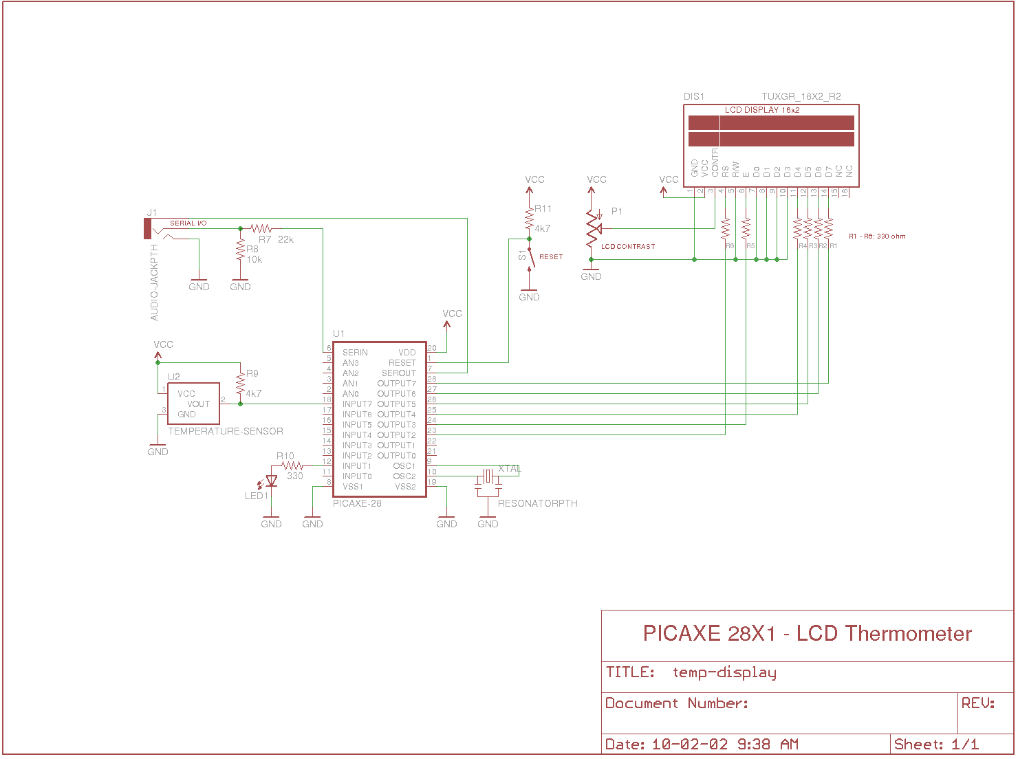
Measures the temperature with DS18B20 temp. sensor and shows on the 2x16 char LCD display, also sends to the serial terminal, and checks against the limits and ...
ghrobotics
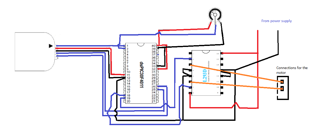
For this experiment I used a light dependant resistor (LDR) to control the speed of a DC motor. I achieved this by means of a voltage divider. I connected in se...

Intelligent Fan Controller
The Intelligent Fan Controller will control the speed of computer fans based on the temperature inside your computer and reduce the noise made by your computer ...

LCD in 4 bit mode with PIC16F877
When you are using LCD in 4 bit mode you have to send data two times where in 8 bit mode you only have to write once, this ultimately keeps your microcontroller...

00 to 99 minute timer using PIC16F628A microcontroller
A source code for a very simple PIC based digital timer. The actual hardware of the project isn`t with me anymore. I will rather demonstrate it using my DIY PIC...

Circuit Diagram of Cheap Programmer
...
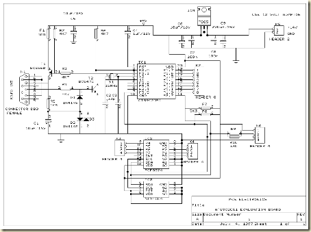
System AT89C2051 and AT89C4051
The circuit is more deserves to be called Evaluation Board AT89C2051 and AT89C4051. Some of the advantages of circuit Minimum System AT89C2051 / AT89C2051 and A...