


Check the three-phase motor with broken bars
#three-phase motor
#broken bars
#motor inspection
#fault detection
#electrical testing
#induction motor
#motor diagnostics
#industrial equipment
#maintenance

Description: The circuit diagram illustrates a three-phase motor equipped with an inspection circuit designed to detect broken bars.
The circuit for a three-phase motor with a broken bar inspection system typically consists of several key components that work together to monitor the health of the motor's rotor. The inspection circuit is crucial for identifying faults that could lead to reduced efficiency or catastrophic failure.
In this setup, the three-phase motor is powered by a three-phase supply, which provides the necessary torque and speed for operation. The inspection circuit includes current sensors placed in each phase line to monitor the current flowing through the motor. These sensors can be Hall effect sensors or current transformers, which provide real-time feedback on the electrical conditions of the motor.
The output from the current sensors is fed into a microcontroller or a dedicated monitoring unit. This unit processes the signals and compares the current readings against predefined thresholds. If the current in any phase deviates significantly from the expected value, it may indicate a broken bar in the rotor. The microcontroller can then trigger an alarm or an indicator light to alert maintenance personnel of the potential issue.
Additional components in the circuit may include resistors for signal conditioning, capacitors for noise filtering, and possibly an interface for communication with a supervisory control and data acquisition (SCADA) system. The design must ensure that the inspection circuit is robust enough to operate under the motor's environmental conditions, which may include vibrations and temperature fluctuations.
In summary, the three-phase motor with a broken bar inspection circuit is an essential system for ensuring reliable motor operation, minimizing downtime, and enhancing overall maintenance practices. As shown in the three-phase motor with broken bars of inspection circuit:
The circuit for a three-phase motor with a broken bar inspection system typically consists of several key components that work together to monitor the health of the motor's rotor. The inspection circuit is crucial for identifying faults that could lead to reduced efficiency or catastrophic failure.
In this setup, the three-phase motor is powered by a three-phase supply, which provides the necessary torque and speed for operation. The inspection circuit includes current sensors placed in each phase line to monitor the current flowing through the motor. These sensors can be Hall effect sensors or current transformers, which provide real-time feedback on the electrical conditions of the motor.
The output from the current sensors is fed into a microcontroller or a dedicated monitoring unit. This unit processes the signals and compares the current readings against predefined thresholds. If the current in any phase deviates significantly from the expected value, it may indicate a broken bar in the rotor. The microcontroller can then trigger an alarm or an indicator light to alert maintenance personnel of the potential issue.
Additional components in the circuit may include resistors for signal conditioning, capacitors for noise filtering, and possibly an interface for communication with a supervisory control and data acquisition (SCADA) system. The design must ensure that the inspection circuit is robust enough to operate under the motor's environmental conditions, which may include vibrations and temperature fluctuations.
In summary, the three-phase motor with a broken bar inspection circuit is an essential system for ensuring reliable motor operation, minimizing downtime, and enhancing overall maintenance practices. As shown in the three-phase motor with broken bars of inspection circuit:

Three-phase squirrel cage motor running single phase connection circuit
The circuit connection is illustrated in figures a and b. In figure a, a star-shaped winding is used with shunt capacitance, while figure b depicts a triangular winding with capacitance connected in parallel. The working capacitance (Cc) is calculated using...

Three-phase motor overcurrent protection circuit
A three-phase electric motor overcurrent protection circuit. This example circuit utilizes a transformer to monitor the current, ensuring that the currents in the three-phase motor do not exceed normal operating levels. When the current exceeds the set threshold, the overcurrent...

Induction-motor control
This single time-constant circuit can be utilized for proportional speed control of induction motors, such as shaded pole or permanent split-capacitor motors, when the load remains constant. The circuit is particularly well-suited for applications that necessitate speed control within the...

Capacitor start single-phase induction motor circuit
Capacitor start single-phase induction motor circuit configuration, in order to form a two-phase rotating magnetic field, starting winding and capacitor in series, the same magnetic field can be formed automatically.
The capacitor start single-phase induction motor utilizes a specific circuit configuration...

130kW induction motor synchronization control circuit operation
The circuit is illustrated. A motor utilizes series resistance in the rotor winding for starting. The drawing includes electrical velocity off the relay KIi ~ KI3 for motor short circuit protection and overcurrent. Additionally, relays 1KI and 2KI provide electrical...

QJ3 series of manually operated auto-voltage start-up circuit
The circuit illustrated in Figure 3-47 involves a three-phase AC motor that is initially connected through a step-down autotransformer. To initiate operation, the power switch is closed, and the operating handle is pushed to the start position. Once the motor...
Capacitor start single-phase induction motor circuit
Capacitor start single-phase induction motor circuit configuration, in order to form a two-phase rotating magnetic field, starting winding and capacitor in series, the same magnetic field can be formed automatically.
The capacitor start single-phase induction motor utilizes a specific circuit configuration...
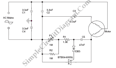
Speed-Control for Small Asynchronous Induction Motor
The circuit diagram below illustrates a schematic designed to control the speed of a low-power induction motor, commonly found in fans.
The schematic for controlling the speed of a low-power induction motor typically incorporates several key components that work together to...

Current three-phase motor phase protection circuit diagram
A current three-phase motor phase protection circuit is designed to detect three-phase current using homemade small current transformers T1, T2, and T3. The current signals are collected by rectifiers VD1, VD2, and VD3, while capacitors C1, C2, and C3 serve...