


Three-phase motor overcurrent protection circuit
#three-phase motor
#overcurrent protection
#current sensing
#transformer
#motor safety
#industrial
#electric motor
#protection circuit
#power electronics
#sensor

Description: A three-phase electric motor overcurrent protection circuit. This example circuit utilizes a transformer to monitor the current, ensuring that the currents in the three-phase motor do not exceed normal operating levels. When the current exceeds the set threshold, the overcurrent relay (K1) activates, causing the normally closed contacts to open. This action results in the loss of power to the contactor (KM), thereby disconnecting the main circuit and protecting the electric motor from damage due to overcurrent. Additionally, to accommodate the high starting current of the motor, a time relay is employed to temporarily short the current transformer, preventing the relay K1 from mistakenly activating during motor startup. Once the motor has started and the current returns to normal levels, the time delay relay (KT) reverts, closing the normally open contacts and allowing K1 to monitor the current transformer circuit once again.
The three-phase electric motor overcurrent protection circuit is designed to safeguard the motor against excessive current conditions that could lead to overheating and failure. The circuit employs a transformer for current sensing, which is crucial for real-time monitoring of the current flowing through each phase of the motor. The overcurrent relay (K1) is calibrated to a specific threshold; if the current exceeds this threshold, K1 activates, opening its normally closed contacts. This action interrupts the power supply to the contactor (KM), effectively disconnecting the motor from the power source and preventing potential damage.
To manage the high inrush current that occurs during motor startup, a time relay is integrated into the circuit. This relay temporarily shorts the current transformer, allowing the motor to start without triggering the overcurrent protection mechanism. This design consideration is essential, as the initial current can be significantly higher than the motor's normal operating current. Once the motor reaches its operational state and the current stabilizes, the time delay relay (KT) resets, enabling K1 to resume monitoring the current levels.
The circuit's design emphasizes reliability and responsiveness, ensuring that the motor is protected without hindering its performance during startup. By incorporating both the current sensing transformer and the time delay relay, the circuit effectively balances protection and operational efficiency, making it suitable for various industrial applications where three-phase motors are utilized. Proper implementation of this protection circuit can significantly extend the lifespan of electric motors and reduce maintenance costs associated with overcurrent-related failures.A three-phase electric motor is over- current protection circuit. How it works: This example circuit uses a transformer to sense the current, three-phase motor currents exceedi ng normal operating current time. Overcurrent relay Kl pull current reaches the set value of the suction, the normally closed contacts disconnect, KM loss of power release, the main circuit power loss t thereby protecting the electric motor, to disconnect when the over-current power supply. When the motor starting current is large, with a time relay normally closed contact to the current transformer shorting avoid motor starting current flows Kl and malfunction.
Motor starting to be completed after the current is reduced to normal, by the delay time relay KT move for the normally closed contacts disconnect, normally open contact closure, the KI access current transformer circuits.
The three-phase electric motor overcurrent protection circuit is designed to safeguard the motor against excessive current conditions that could lead to overheating and failure. The circuit employs a transformer for current sensing, which is crucial for real-time monitoring of the current flowing through each phase of the motor. The overcurrent relay (K1) is calibrated to a specific threshold; if the current exceeds this threshold, K1 activates, opening its normally closed contacts. This action interrupts the power supply to the contactor (KM), effectively disconnecting the motor from the power source and preventing potential damage.
To manage the high inrush current that occurs during motor startup, a time relay is integrated into the circuit. This relay temporarily shorts the current transformer, allowing the motor to start without triggering the overcurrent protection mechanism. This design consideration is essential, as the initial current can be significantly higher than the motor's normal operating current. Once the motor reaches its operational state and the current stabilizes, the time delay relay (KT) resets, enabling K1 to resume monitoring the current levels.
The circuit's design emphasizes reliability and responsiveness, ensuring that the motor is protected without hindering its performance during startup. By incorporating both the current sensing transformer and the time delay relay, the circuit effectively balances protection and operational efficiency, making it suitable for various industrial applications where three-phase motors are utilized. Proper implementation of this protection circuit can significantly extend the lifespan of electric motors and reduce maintenance costs associated with overcurrent-related failures.A three-phase electric motor is over- current protection circuit. How it works: This example circuit uses a transformer to sense the current, three-phase motor currents exceedi ng normal operating current time. Overcurrent relay Kl pull current reaches the set value of the suction, the normally closed contacts disconnect, KM loss of power release, the main circuit power loss t thereby protecting the electric motor, to disconnect when the over-current power supply. When the motor starting current is large, with a time relay normally closed contact to the current transformer shorting avoid motor starting current flows Kl and malfunction.
Motor starting to be completed after the current is reduced to normal, by the delay time relay KT move for the normally closed contacts disconnect, normally open contact closure, the KI access current transformer circuits.

CENTER TAPPED TRANSFORMER AUDIO OSCILLATOR
The oscillator circuit employs a center-tapped transistor output transformer that functions as a load for the collector of Q1, provides a feedback signal to the base, and acts as the output winding to drive the speaker. Resistor R1 supplies DC...

Wire Break Sensor Alarm Circuit Schematic
The circuit of a loop sensor-based simple security alarm is described here. The sensor loop consists of a short length of thin enamelled copper wire.
The loop sensor security alarm operates on the principle of detecting interruptions in the circuit formed...

Current sensing of the rails circuit diagram
The LTC1043 can be induced through any of its current shunt supply rails. Many cells and solar system applications have this feature. If the reference point is grounded, the voltage output of an unloaded amplifier is minimal, allowing the rail...

A three-phase motor phase automatic protection circuit
Connect a transformer to the motor phase line when the induced voltage is zero volts. In cases of serious imbalance in one, two, or three phases, the transformer’s induced voltage increases rapidly, which leads to an immediate rectification of the...

Electrical transformer tutorial
Afroman explains the fundamentals of transformer operation, where to purchase step-down mains transformers, and how to safely wire one to mains voltages. The discussion includes both European and North American wiring standards. The presentation concludes with a brief example of...

Current sense schematic question
Exploring various methods for current sensing using standard operational amplifiers instead of specialized chips like the MAX4073T/F/H, which perform well but are relatively expensive. An article by Bob Pease discussing "error budgets" caught attention, particularly Figure Two of the schematic,...

Two electric motors on the mechanical brake circuit
The circuit depicted in Figure 3-157 is designed for motors with a capacity of no more than 11 kW, requiring precise stopping capabilities. Upon shutdown, contact KMi releases, and the motor stator windings are configured into a three-phase rectifier circuit...

Gate automatic lamp circuit
The circuit utilizes multiple integrated circuits to form an automatic lighting device that is activated by door and window sensors. It includes CD4093 digital integrated circuits, a relay, and a power supply circuit. The system typically remains closed when a...
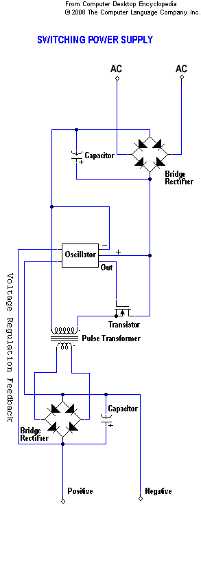
transformer circuit
A static device that couples two circuits to transfer alternating current (AC) from one circuit to another through electromagnetic induction. The current maintains the same frequency but may vary in voltage, phase, or impedance values. A transformer consists of two...