


Two Phase Bipolar Stepper Motor Control
#stepper motor
#L6506
#L298
#bipolar
#current controller
#motor driver
#two phase
#control circuit
#driving signals

Description: The following figure illustrates the control circuit for a two-phase bipolar stepper motor utilizing the current controller L6506. The L6506 integrated circuit generates the necessary signals to drive the inputs of the L298 bipolar stepper motor circuit driver.
The circuit in question employs the L6506 current controller to manage the operation of a two-phase bipolar stepper motor. The L6506 is designed to provide precise current control, which is crucial for the efficient operation of stepper motors. This integrated circuit outputs the control signals that dictate the timing and magnitude of the current supplied to the motor phases, ensuring smooth and accurate stepping.
The L298 is a dual H-bridge motor driver capable of controlling the direction and speed of the stepper motor. It receives the control signals from the L6506, which are generated based on the desired stepping sequence and motor control parameters. The L298 is capable of driving the motor in both forward and reverse directions while providing the necessary current to each phase of the motor.
In this configuration, the L6506 monitors the current flowing through the motor coils and adjusts the PWM (Pulse Width Modulation) signals sent to the L298 accordingly. This feedback mechanism allows for precise control over the motor's performance, reducing the risk of overheating and enhancing efficiency. The circuit typically includes additional components such as diodes for flyback protection and capacitors for stability, ensuring reliable operation in various conditions.
Overall, this driving circuit effectively combines the functionalities of the L6506 and L298 to deliver a robust solution for controlling two-phase bipolar stepper motors, suitable for applications requiring accurate positioning and smooth motion control.The following figure shown the driving of two phase bipolar stepper motor control circuit by using the current controller L6506. The IC L506 generates the needed signals to drive the inputs of the L298 of this bipolar stepper motor circuit driver
The circuit in question employs the L6506 current controller to manage the operation of a two-phase bipolar stepper motor. The L6506 is designed to provide precise current control, which is crucial for the efficient operation of stepper motors. This integrated circuit outputs the control signals that dictate the timing and magnitude of the current supplied to the motor phases, ensuring smooth and accurate stepping.
The L298 is a dual H-bridge motor driver capable of controlling the direction and speed of the stepper motor. It receives the control signals from the L6506, which are generated based on the desired stepping sequence and motor control parameters. The L298 is capable of driving the motor in both forward and reverse directions while providing the necessary current to each phase of the motor.
In this configuration, the L6506 monitors the current flowing through the motor coils and adjusts the PWM (Pulse Width Modulation) signals sent to the L298 accordingly. This feedback mechanism allows for precise control over the motor's performance, reducing the risk of overheating and enhancing efficiency. The circuit typically includes additional components such as diodes for flyback protection and capacitors for stability, ensuring reliable operation in various conditions.
Overall, this driving circuit effectively combines the functionalities of the L6506 and L298 to deliver a robust solution for controlling two-phase bipolar stepper motors, suitable for applications requiring accurate positioning and smooth motion control.The following figure shown the driving of two phase bipolar stepper motor control circuit by using the current controller L6506. The IC L506 generates the needed signals to drive the inputs of the L298 of this bipolar stepper motor circuit driver

Focusser
Create an electronic focuser to assist with astrophotography. This electronic focuser project enables precise focusing under computer control, which is particularly beneficial for eyepiece projection astrophotography. It was observed that even minor contact with the focuser could displace the object...

Three-phase stepper motor control circuit
The figure illustrates that the DC Solid State Relay (SSR) in the input stage functions as an opto-isolator. When the switch output is high, the driver circuit inverts this signal to low. This process involves a light-emitting diode (LED) where...

can rotate stepper motor
A stepper motor is to be rotated using a Johnson counter 4017 integrated circuit (IC). A bipolar stepper motor is utilized, with connections made from pins 3, 2, 4, and 7 of the 4017 IC following a specific sequence.
The circuit...

A BIPOLAR REGENERATIVE RECEIVER
Contrary to the beliefs of some radio experimenters, an efficient bipolar regenerative design is achievable. The primary concern lies in the low input impedance of the detector-amplifier bipolar stage. However, this can be effectively compensated for with positive feedback or...

Stepper Motor Controller
I found this circuit in my files. I don't know where it came from, but it looks like I photocopied it from somewhere years ago. I have been told that it came from "The Robot Builder's Bonanza", by Gordan McComb....

Stepper Motor Driver
These motors consist of two coils and are operated by altering the direction of current flow through the coils in a specific sequence. They feature only four wires and cannot be directly connected to this kit. Refer to Kit 1406...

Dual Axis Stepper Motor Controller
This document details a dual-axis stepper motor controller design and printed circuit board for an equatorial mount. Acknowledgment is given to Bill Prewitt for his assistance in creating this webpage. An encapsulated PostScript file containing the artwork for both sides...

Parallel Port Stepper Motor Driver With Discrete Components
The use of a PC's parallel port provides a convenient method for controlling a stepper motor. For unipolar stepper motors, it is possible to control up to two motors using the 8-bit data line. Typically, a Darlington driver, such as...
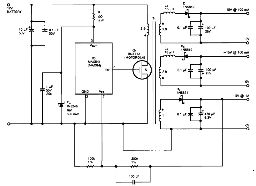
bipolar 15 v and 5v from car battery supply
Bipolar +/- 15V and 5V from car battery supply power supply. Refer to the specified page for an explanation of the related circuit diagram.
The described power supply circuit is designed to provide bipolar voltage outputs of +/- 15V and a...