


unipolar stepper motor controller
#stepper motor
#motor driver
#compact design
#direction control
#stepping pulses
#integrated circuit
#5-wire
#6-wire
#8-wire

Description: This integrated circuit is highly efficient and does not require any external glue logic for operation. It features two pins for motor control: one pin is dedicated to controlling the direction of the motor, while the other pin is used to trigger the stepping pulses. The design is compact and capable of driving 5, 6, or 8 wire stepper motors.
The integrated circuit in question is designed to facilitate the operation of stepper motors, which are commonly used in applications requiring precise control of angular position. The two control pins simplify the interface, eliminating the need for additional components typically required for motor control, such as logic gates or microcontroller outputs.
The direction control pin allows for easy reversal of the motor's rotation, enabling applications that require bidirectional movement. The pulse triggering pin generates the necessary stepping signals, which dictate the speed and position of the motor. By adjusting the frequency of the pulses sent to this pin, the speed of the stepper motor can be finely tuned to meet specific operational requirements.
This integrated circuit supports various configurations of stepper motors, including 5, 6, and 8 wire types. The ability to drive different motor configurations enhances its versatility, making it suitable for a wide range of applications, from robotics to CNC machinery. The compact nature of the design also contributes to space-saving in electronic assemblies, making it an ideal choice for modern, compact devices.
In summary, this integrated circuit provides an efficient and straightforward solution for driving stepper motors, offering enhanced control with minimal external circuitry. Its design allows for a seamless integration into various electronic systems, ensuring reliable performance in demanding applications.This is a very good integrated circuit. There is no need for any external glue logic to drive the circuit, there is only 2 pins to drive the motor, one for controlling the direction and the other to trigger the stepping pulses. It provides a very compact design that drives 5 or 6 or 8 wire stepper motors..
The integrated circuit in question is designed to facilitate the operation of stepper motors, which are commonly used in applications requiring precise control of angular position. The two control pins simplify the interface, eliminating the need for additional components typically required for motor control, such as logic gates or microcontroller outputs.
The direction control pin allows for easy reversal of the motor's rotation, enabling applications that require bidirectional movement. The pulse triggering pin generates the necessary stepping signals, which dictate the speed and position of the motor. By adjusting the frequency of the pulses sent to this pin, the speed of the stepper motor can be finely tuned to meet specific operational requirements.
This integrated circuit supports various configurations of stepper motors, including 5, 6, and 8 wire types. The ability to drive different motor configurations enhances its versatility, making it suitable for a wide range of applications, from robotics to CNC machinery. The compact nature of the design also contributes to space-saving in electronic assemblies, making it an ideal choice for modern, compact devices.
In summary, this integrated circuit provides an efficient and straightforward solution for driving stepper motors, offering enhanced control with minimal external circuitry. Its design allows for a seamless integration into various electronic systems, ensuring reliable performance in demanding applications.This is a very good integrated circuit. There is no need for any external glue logic to drive the circuit, there is only 2 pins to drive the motor, one for controlling the direction and the other to trigger the stepping pulses. It provides a very compact design that drives 5 or 6 or 8 wire stepper motors..
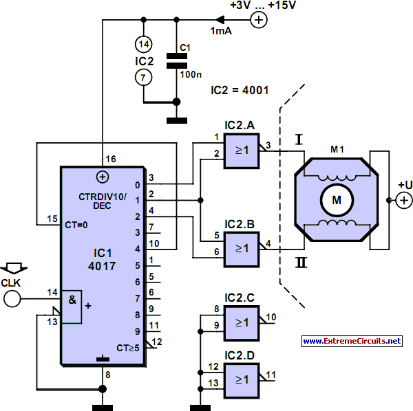
Stepper Motor Generator
Stepper motors are a recurring subject. This circuit converts a clock signal from a square wave generator into signals with a 90-degree phase shift.
Stepper motors are widely used in applications requiring precise control of angular position, speed, and acceleration. The...

The "BEAM Stepper" drive circuit
The 74AC240 stepper driver works by alternately enabling each half of the buffer. Only one half can be enabled at a time.
Let’s assume that the top half of the driver is enabled. U1A & U1B along with R8, C1,...

Stepper Motor Project
The microcontroller board is displayed (top left/green board) alongside the auxiliary board (bottom left/brown board) and two geared Hurst stepper motors. In this view, the programming jumper is located in the upper right area of the microcontroller board, while power...

Big Trak Motor Driver Schematic
Schematic of Big Trak's motor driver circuit. The toy includes 9112 and 9113 transistors (and sometimes 2N6715) because the 75494 chip cannot supply enough current to run the Big Trak's motors by itself.
The motor driver circuit for the Big Trak...

A Unipolar Stepper Motor Driver
The drive circuits for unipolar stepper motors are typically straightforward. In their simplest configuration, a transistor or MOSFET is employed to control each section of the windings. The control signal must be supplied programmatically to the four windings of the...

stepper motor control
The 3D printer necessitates independent control for three separate axes. Each controlled axis must be equipped with a high-precision electronic driver. The mechanical components of each axis utilize a precise bipolar stepper motor connected to a drive shaft via a...

Current amplification for driving stepper motor
In the search for stepper drivers, the ULN2003 chip was discovered, which facilitates motor operation with minimal circuitry through the parallel port of a PC. However, the current output from the ULN2003 is limited to 500mA, resulting in low torque,...
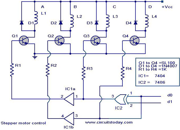
Stepper motor controller - Driver circuit with circuit design
The circuit diagram illustrates a simple stepper motor controller utilizing basic components. The driver circuit employs four SL100 transistors to control the motor windings, along with two NOT gates and one XOR gate to decode the two-bit control logic needed...

Controlling stepper motors
The first pulse motor that is used to position control. Features were incorporated for positioning control. This does not mean intelligent and autonomous driving the motor in response to movement commands from the host. The key to controlling the pulse...