


a voltage-controlled current sink / voltage-controlled resistor
#voltage-controlled
#current sink
#LM324
#TLC5940
#Howland current source
#potentiometer
#current mirror
#LED dimming
#voltage source
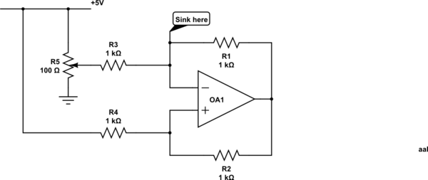
Description: Control a current through several current-mirror devices (specifically the IREF pin on the TLC5940) using a single potentiometer. A modified Howland current source has been utilized, which works adequately with the specified resistor values for dimming an LED. However, it fails to function as a current sink with a 1.24V voltage source at the designated sink node. The circuit employs an LM324 quad op-amp. Suggestions are sought for exploring options for a voltage-controlled current sink, voltage-controlled resistor (VCR), or an R-controlled resistor. A minimalist circuit is desired to control at least six current mirrors (TLC5940s) with a single potentiometer, and accuracy is not a critical requirement. While VCRs have been constructed using photocells and LEDs, this approach is considered cumbersome. An optocoupler is also a potential solution, but linearity may pose challenges. A MOSFET can serve as a voltage-controlled resistor, provided it does not dissipate excessive power, although the resistance would be relatively small. Concerns have been raised about biasing issues in MOSFET/JFET circuits, and it is noted that non-linearity can potentially be mitigated by feeding the drain to the gate through a resistor. Variations in manufacturing within a single batch of MOSFETs may lead to significant differences in the linear characteristics and gate capacitance, complicating parallel operation of multiple FET-resistors driven from a single signal.
The circuit design addresses the need to regulate current through multiple current-mirror devices using a single adjustable control element. The TLC5940, a serial LED driver, requires precise control of the reference current at its IREF pin. The proposed approach employs a modified Howland current source, which is a configuration often used for current sources due to its ability to provide stable output current. However, the circuit's limitation as a current sink at a specified voltage necessitates alternative solutions.
To create a voltage-controlled current sink, several methods could be explored. One approach is to utilize a MOSFET in the linear region of operation, where it can be configured as a voltage-controlled resistor. The gate voltage can be adjusted via the potentiometer, allowing for control over the drain current. Care must be taken to ensure that the MOSFET operates within its safe limits, as excessive power dissipation could lead to thermal issues.
Another potential solution is the use of an optocoupler, which could facilitate isolation between the control circuit and the current mirror. However, the linearity of the output current in relation to the input control voltage may need to be characterized to ensure adequate performance.
For applications requiring minimal complexity, a design incorporating a single potentiometer to control multiple TLC5940 devices can be advantageous. The circuit could be designed such that the output from the potentiometer is fed into a summing amplifier or a buffer stage before being distributed to the IREF pins of the TLC5940s. This would maintain a consistent reference current across all devices, simplifying the control mechanism.
In summary, the design challenge involves creating a reliable and efficient voltage-controlled current sink that can manage multiple current mirrors with minimal complexity while addressing potential issues related to linearity and component variability.Control a current through several current-mirror device (specifically the IREF pin on the TLC5940 ) using a single potentiometer. I`ve tried using a modified Howland current souce as in the following schematic: While this works OK with resistor values as shown for dimming a LED, it doesn`t work as a current sink given a 1.
24V voltage source at the node marked sink. I am using an LM324 quad op-amp. If someone can suggest some avenues to explore for a voltage controlled I-sink, or voltage-controlled resistor (VCR), or an R-controlled resistor, etc. I would appreciate it. I`d like a minimalist circuit, if possible, as I`ll need to control at least six current mirrors (TLC5940s) for my application, with a single pot/trimmer, and accuracy is not really critical in this application.
People seem to have built VCRs out of photocells + LEDs, however, this seems a bit cludgey. I suppose an optocoupler is an option, however, I think linearity will be an (admitedly not huge) issue. A MOSFET can be used as a voltage controlled resistor, as long as it doesn`t dissipate too much power - although, this would be a fairly small resistance.
Kurt E. Clothier May 19 `13 at 2:15 People seem to complain about MOSFET/JFET circuits because of biasing issues, I guess. It seems that non-linearity can be overcome by feeding the drain to the gate through a resistor, right Do you want to make your comment into an answer angelatlarge May 19 `13 at 2:28 Something like that.
I`ve seen it done, but I don`t understand it quite enough to make a full answer. Maybe someone else can come up with something more definitive. Kurt E. Clothier May 19 `13 at 2:41 @angelatlarge From a prior experiment, the variation in manufacturing within a single batch of MOSFETs may give wide differences in the linear part of the curve, and in gate capacitance (therefore charging time) across MOSFETs. This adds a big challenge to any meaningful "parallel operation" of multiple FET-resistors driven from a single signal.
Anindo Ghosh May 19 `13 at 5:44
The circuit design addresses the need to regulate current through multiple current-mirror devices using a single adjustable control element. The TLC5940, a serial LED driver, requires precise control of the reference current at its IREF pin. The proposed approach employs a modified Howland current source, which is a configuration often used for current sources due to its ability to provide stable output current. However, the circuit's limitation as a current sink at a specified voltage necessitates alternative solutions.
To create a voltage-controlled current sink, several methods could be explored. One approach is to utilize a MOSFET in the linear region of operation, where it can be configured as a voltage-controlled resistor. The gate voltage can be adjusted via the potentiometer, allowing for control over the drain current. Care must be taken to ensure that the MOSFET operates within its safe limits, as excessive power dissipation could lead to thermal issues.
Another potential solution is the use of an optocoupler, which could facilitate isolation between the control circuit and the current mirror. However, the linearity of the output current in relation to the input control voltage may need to be characterized to ensure adequate performance.
For applications requiring minimal complexity, a design incorporating a single potentiometer to control multiple TLC5940 devices can be advantageous. The circuit could be designed such that the output from the potentiometer is fed into a summing amplifier or a buffer stage before being distributed to the IREF pins of the TLC5940s. This would maintain a consistent reference current across all devices, simplifying the control mechanism.
In summary, the design challenge involves creating a reliable and efficient voltage-controlled current sink that can manage multiple current mirrors with minimal complexity while addressing potential issues related to linearity and component variability.Control a current through several current-mirror device (specifically the IREF pin on the TLC5940 ) using a single potentiometer. I`ve tried using a modified Howland current souce as in the following schematic: While this works OK with resistor values as shown for dimming a LED, it doesn`t work as a current sink given a 1.
24V voltage source at the node marked sink. I am using an LM324 quad op-amp. If someone can suggest some avenues to explore for a voltage controlled I-sink, or voltage-controlled resistor (VCR), or an R-controlled resistor, etc. I would appreciate it. I`d like a minimalist circuit, if possible, as I`ll need to control at least six current mirrors (TLC5940s) for my application, with a single pot/trimmer, and accuracy is not really critical in this application.
People seem to have built VCRs out of photocells + LEDs, however, this seems a bit cludgey. I suppose an optocoupler is an option, however, I think linearity will be an (admitedly not huge) issue. A MOSFET can be used as a voltage controlled resistor, as long as it doesn`t dissipate too much power - although, this would be a fairly small resistance.
Kurt E. Clothier May 19 `13 at 2:15 People seem to complain about MOSFET/JFET circuits because of biasing issues, I guess. It seems that non-linearity can be overcome by feeding the drain to the gate through a resistor, right Do you want to make your comment into an answer angelatlarge May 19 `13 at 2:28 Something like that.
I`ve seen it done, but I don`t understand it quite enough to make a full answer. Maybe someone else can come up with something more definitive. Kurt E. Clothier May 19 `13 at 2:41 @angelatlarge From a prior experiment, the variation in manufacturing within a single batch of MOSFETs may give wide differences in the linear part of the curve, and in gate capacitance (therefore charging time) across MOSFETs. This adds a big challenge to any meaningful "parallel operation" of multiple FET-resistors driven from a single signal.
Anindo Ghosh May 19 `13 at 5:44

Tremolo
A phase shift oscillator utilizing the LM324 operates at an adjustable frequency range of 5-10 Hz, which is determined by a speed potentiometer. A segment of the oscillator output is extracted from the depth potentiometer and is employed to modulate...

Automobile Interior Lights Fader circuit
The circuit utilizes the LM324 low-power operational amplifier, which consumes approximately 3mA of current. This low current draw ensures that the battery will not be adversely affected if the circuit remains connected for extended durations.
The LM324 is a quad operational...

Make Lm324 Op Amp Swing Rail-To-Rail
By utilizing two CMOS inverters, the output voltage of an LM324 operational amplifier can be increased from 3.5 V peak-to-peak (Vpp) to 4.9 Vpp. This circuit is recommended solely for light loads (less than 30 mA) and for relatively slow...

Voltage-controlled Current-limited switcher circuit
The product requires a voltage-controlled, current-limited power supply. Various switcher chips have been used with an op-amp to provide feedback for a current sense voltage to the feedback pin. Currently, an LM22680 is in use, but it has shown inconsistent...

LM324 Water Level Sensor/Indicator
This is a hot water level indicator circuit. This circuit can be used to monitor the level of hot water in a tank. It is simple and inexpensive.
The hot water level indicator circuit is designed to provide a reliable method...

FUZZ_CIRCUIT
Two diodes in the feedback path of an LM324 operational amplifier create a musical instrument effect known as fuzz by limiting the output voltage swing to ±0.7 V. The resultant square wave primarily contains odd harmonics, resembling the sounds of...

LM324 For Parking Sensor
The following circuit illustrates the use of the LM324 in a parking sensor circuit diagram. Features: When the obstacle is beyond 25 cm, none of the above LEDs will activate.
The LM324 is a quad operational amplifier that is commonly used...

potentiometer Making an adjustable resistance
This part of the circuit is isolated from any other component, except for the 5V and ground connections. It includes LEDs and a shift register, which may not interact significantly. The LDR (Light Dependent Resistor) is utilized solely as a...
amplifier tutorial
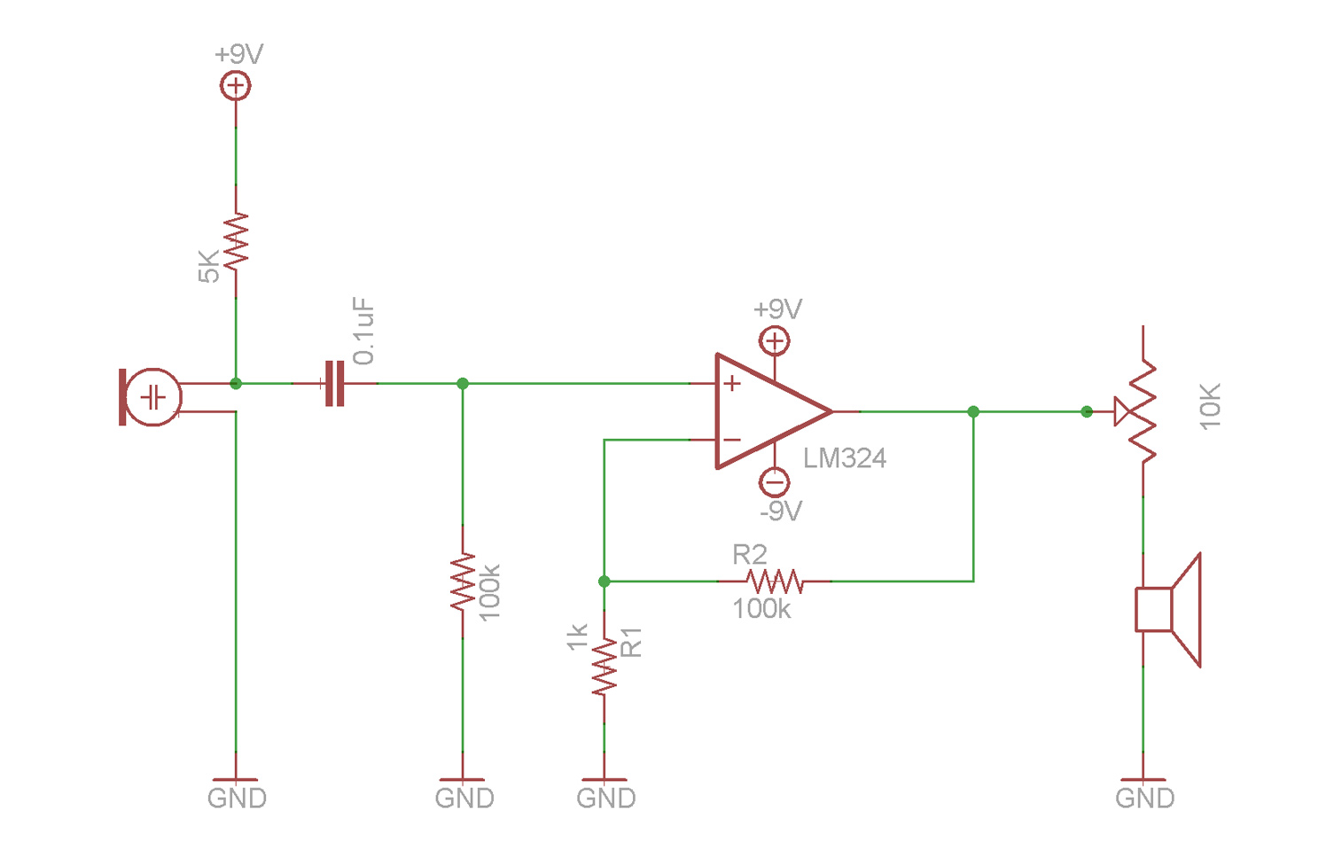
This video demonstrates the fundamentals of operational amplifiers (op amps) and includes an example circuit that amplifies a small microphone signal to make it audible through earbuds. The circuit utilizes the LM324 quad op amp integrated circuit (IC).
The described circuit...