


Functional Block Diagram for AD524 pin and internal circuit
#AD524
#low-drift
#low-noise
#high CMRR
#gain bandwidth
#precision amplifier
#signal conditioning
#instrumentation

Description: The AD524 is a low-drift instrumentation amplifier characterized by a drift voltage of 0.5 mV and a maximum drift of 25 mV at room temperature. It has low noise performance with a noise level of 0.3 mVp-p in the frequency range of 0.1 to 10 Hz. The amplifier exhibits good linearity with a typical value of 0.0030 at a gain of 1, and it features a high common-mode rejection ratio (CMRR) of 120 dB. The gain bandwidth is 25 MHz, and it offers adjustable gain settings of 1, 10, 100, and 1000. The output slew rate is specified at 5 V/ms, making it suitable for precision instrumentation applications. The power supply range for the AD524 is from 6 to 18 V. The internal circuit includes input protection and output amplification, allowing the device to differentiate between sub-gain settings and the main gain configuration. The signal input is first processed through a pre-release stage before being amplified by the differential instrumentation amplifier. The gain can be set accurately at 10 or 100 when the appropriate pins are connected, with a default gain of 1 when no additional connections are made. Moreover, the feedback input resistor can be adjusted to modify the amplifier's gain, making the AD524 a convenient choice for non-standard gain adjustment in instrumentation applications.
The AD524 low-drift instrumentation amplifier is designed for high-precision applications requiring minimal drift and noise characteristics. With a drift voltage of just 0.5 mV, this amplifier maintains stability in various operating conditions, making it ideal for sensitive measurements. The low noise level of 0.3 mVp-p ensures that the signal integrity is preserved across a wide frequency range, particularly in low-frequency applications where noise can significantly impact performance.
The amplifier's linearity is critical for applications that demand accurate signal reproduction. With a linearity specification of 0.0030 at a gain of 1, users can expect reliable performance across different gain settings. The high CMRR of 120 dB further enhances the amplifier's ability to reject common-mode signals, which is essential in environments with significant electrical noise.
The adjustable gain feature allows users to configure the amplifier for a variety of applications, ranging from low-gain settings of 1 to high-gain settings of 1000. This versatility is complemented by the amplifier's gain bandwidth of 25 MHz, ensuring that it can handle fast signal changes without distortion. The output slew rate of 5 V/ms indicates that the amplifier can respond quickly to input signal variations, making it suitable for dynamic measurement scenarios.
The internal architecture of the AD524 includes essential protective features that safeguard the input and output stages, ensuring long-term reliability. The pre-release stage processes the incoming signal before amplification, which helps to minimize distortion and improve overall performance. The differential instrumentation amplifier configuration allows for precise amplification of small signals in the presence of noise.
In terms of power supply requirements, the AD524 operates within a range of 6 to 18 V, making it compatible with various power supply designs. This flexibility allows for easy integration into existing systems without the need for extensive modifications.
Overall, the AD524 low-drift instrumentation amplifier is a robust solution for applications requiring high precision, low noise, and adjustable gain settings, making it a valuable component in the field of electronic instrumentation.AD524 low-drift (drift voltage 0.5mV, maximum drift 25 mV door C), low noise (0.3mVp p, 0.1-10Hz), good linearity ( 0.0030/0, a gain of l), high CMRR (120dB) gain bandwidth of 25MHz, stepper adjustable gain (gain 1,10,100,1000), output slew rate of 5V/ms precision instruments put amplifier. Power supply range is (6 ~ 18V). The pin and internal circuit functional block diagram in Fig. 10 - 10. AD524 internally by input protection, output amplification recognize the difference between sub-gain instrumentation amplifier and setting circuit, and the like.
Signal after, pin input is first pre-release, and then by the differential instrument is an amplified output from a feet., ?, ? feet respectively connection feet, accurately set the internal amplifier gain set to 10, 100, when not connected to a gain of foot 1.
In addition, these pins or re-train people in resistance when, ? pin feedback input resistor is connected, can be adjusted gain of the amplifier. Therefore, AD524 is a gain adjustment of non- regular convenient instrumentation amplifier.
The AD524 low-drift instrumentation amplifier is designed for high-precision applications requiring minimal drift and noise characteristics. With a drift voltage of just 0.5 mV, this amplifier maintains stability in various operating conditions, making it ideal for sensitive measurements. The low noise level of 0.3 mVp-p ensures that the signal integrity is preserved across a wide frequency range, particularly in low-frequency applications where noise can significantly impact performance.
The amplifier's linearity is critical for applications that demand accurate signal reproduction. With a linearity specification of 0.0030 at a gain of 1, users can expect reliable performance across different gain settings. The high CMRR of 120 dB further enhances the amplifier's ability to reject common-mode signals, which is essential in environments with significant electrical noise.
The adjustable gain feature allows users to configure the amplifier for a variety of applications, ranging from low-gain settings of 1 to high-gain settings of 1000. This versatility is complemented by the amplifier's gain bandwidth of 25 MHz, ensuring that it can handle fast signal changes without distortion. The output slew rate of 5 V/ms indicates that the amplifier can respond quickly to input signal variations, making it suitable for dynamic measurement scenarios.
The internal architecture of the AD524 includes essential protective features that safeguard the input and output stages, ensuring long-term reliability. The pre-release stage processes the incoming signal before amplification, which helps to minimize distortion and improve overall performance. The differential instrumentation amplifier configuration allows for precise amplification of small signals in the presence of noise.
In terms of power supply requirements, the AD524 operates within a range of 6 to 18 V, making it compatible with various power supply designs. This flexibility allows for easy integration into existing systems without the need for extensive modifications.
Overall, the AD524 low-drift instrumentation amplifier is a robust solution for applications requiring high precision, low noise, and adjustable gain settings, making it a valuable component in the field of electronic instrumentation.AD524 low-drift (drift voltage 0.5mV, maximum drift 25 mV door C), low noise (0.3mVp p, 0.1-10Hz), good linearity ( 0.0030/0, a gain of l), high CMRR (120dB) gain bandwidth of 25MHz, stepper adjustable gain (gain 1,10,100,1000), output slew rate of 5V/ms precision instruments put amplifier. Power supply range is (6 ~ 18V). The pin and internal circuit functional block diagram in Fig. 10 - 10. AD524 internally by input protection, output amplification recognize the difference between sub-gain instrumentation amplifier and setting circuit, and the like.
Signal after, pin input is first pre-release, and then by the differential instrument is an amplified output from a feet., ?, ? feet respectively connection feet, accurately set the internal amplifier gain set to 10, 100, when not connected to a gain of foot 1.
In addition, these pins or re-train people in resistance when, ? pin feedback input resistor is connected, can be adjusted gain of the amplifier. Therefore, AD524 is a gain adjustment of non- regular convenient instrumentation amplifier.

Signal Conditioning Circuit for KMI 15/x Rotation Speed Sensor
A modulated current is supplied by the integrated rotational speed sensor KMI 15/x. This current signal needs to be converted into a ground-referenced voltage signal.
The KMI 15/x sensor operates by generating a modulated current proportional to the rotational speed of...

ADT70 internal functional block diagram
The ADI I70 is a signal conditioning integrated circuit designed for RTD/PRTD applications, particularly suitable for 1K and 100Ω platinum RTDs (PRTDs). The ADT70 features an integrated instrumentation amplifier, an operational amplifier, a 2.5V reference power supply, and a matching...

Digitally-programmable-precision-amplifier
The DG419 considers the high input impedance of the operational amplifier, making the effects of Rvs negligible. The DG441 is also connected in series with RIN and is not included in the feedback dividers, thereby contributing negligible error to the...

Signal Conditioning Analog Front-end for Microcontrollers
The I/O board incorporates 16-bit resolution voltage analog inputs and outputs, along with a 4-20mA current loop transmitter and receiver for microcontroller applications. The document discusses amplifier circuits and schematics, including a signal conditioning variable gain amplifier, analog filter, and...

Signal Conditioners Information
Signal conditioning involves a series of operations applied to a signal to make it compatible for interfacing with other devices or systems. Signal conditioners are the devices that execute this operation, featuring both an input and an output. Typically, the...

Signal-conditioner-with-bridge
The LT1007 is capable of providing excitation current directly to bias the 350-0 bridge at 5 V. With only 5 V across the bridge, as opposed to the usual 10 V, total power dissipation and bridge warm-up drift is reduced....
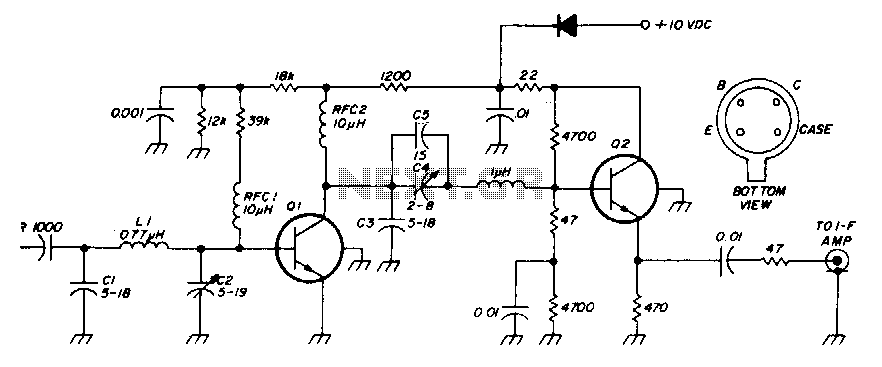
Low-noise 30Mhz preamplifier
The low-noise preamplifier features a noise figure of 1 dB at 30 MHz and a 3 dB bandwidth of 10 MHz. The gain is 19 dB. The total current drain with a +10 volt supply is 13 mA. The resistors...

Low-noise preamplifier circuit
Low-noise preamplifier circuit. This circuit demonstrates a typical low-noise preamplifier design, which can be utilized to amplify signals from sources such as magnetic heads and microphones within audio applications. The input signal is coupled through a capacitor and subsequently passed...

Digital Controlled Precision Amplifier Circuit PCB
This circuit is a precision amplifier with digital control, designed for signal conditioning of low-output transducers operating in the millivolt range. The resistors R3 to R6 can be user-selected, with values ranging from 1 kilo-ohm to 1 mega-ohm, allowing for...