


Input pulse width controller circuit
#pulse width control
#LM3900
#operational amplifier
#comparator
#ramp generator
#1 kHz oscillator
#single supply
#pulse train
#control voltage

Description: The quad operational amplifier circuit provides a pulse width modulation control ranging from 0 to 100 percent. The controller utilizes an LM3900 and operates with a single supply voltage between 4 to 30 V. A 1 kHz oscillator amplifier, which integrates AI, sets the pulse repetition frequency. This oscillator feeds into an Az ramp generator that produces a linear ramp voltage for each pulse. The ramp signal is applied to the inverting input of comparator A3, while the control voltage is connected to the non-inverting input. Consequently, the output of the comparator generates a 1 kHz pulse train, with the pulse width varying linearly according to the control voltage. The control voltage can be supplied through an adjustable potentiometer or an external feedback source, such as an engine speed detection circuit. Depending on the control voltage setting, the pulse duration can be adjusted from zero (resulting in no average DC voltage applied to the motor) to the full repetition period of the pulses (where the voltage applied to the motor equals the DC power supply voltage). An amplifier stage (A4) with a gain of 10 functions as a pulse squaring circuit. A TIP-31 medium-power transistor is driven by A4, serving as a dedicated power amplification stage.
The described quad operational amplifier circuit serves as an efficient pulse width modulation controller, leveraging the LM3900 operational amplifier to achieve precise control of motor speed or other applications requiring variable power delivery. The single supply voltage range of 4 to 30 V allows for versatile integration across various electronic systems. The core of the circuit is the 1 kHz oscillator amplifier, which serves to generate a stable frequency for the pulse width modulation.
The Az ramp generator plays a crucial role in producing a linear voltage ramp, which is essential for generating the desired pulse width. By applying this ramp signal to the inverting input of comparator A3, the circuit can effectively compare the ramp voltage with the control voltage. The comparator's output produces a pulse train whose width is modulated in accordance with the control voltage. This feature enables the circuit to adapt to different operational requirements, such as varying motor speeds based on external conditions or user input.
The adjustable potentiometer or external feedback source can be integrated into the circuit to provide dynamic control over the pulse width. This adaptability allows for real-time adjustments, making the circuit suitable for applications such as motor speed control in automotive systems or other machinery where speed regulation is critical.
The amplifier stage A4, with its gain of 10, functions as a pulse squaring circuit, ensuring that the output pulse train is sharp and well-defined, which is vital for driving the subsequent TIP-31 transistor. This medium-power transistor acts as a power amplifier, capable of handling significant current loads while providing efficient power delivery to the motor or other connected loads. The overall design of the circuit emphasizes reliability and performance, making it a valuable component in various electronic control systems.The quad operational amplifier circuit yields full 0 to 100 percent pulse width control. The controller uses an LM3900 requires only a single supply voltage of 4-30 V. The pulse repetition frequency is set by a 1 kHz oscillator amplifier that integrates AI. The oscillator feeds the Az ramp generator, which generates a linear ramp voltage for each pulse oscillator. The ramp signal feeds the inverting input of comparator A3, the control voltage feeds speed non-inverting input.
Thus, the output of the comparator is a 1 kHz pulse train, pulse width that changes linearly with control voltage. The control voltage may be provided by a _ adjustable potentiometer or an external source of feedback as an engine speed detection circuit. Depending on the setting of control voltage, the pulse duration can be set at a value between zero (zero average dc voltage applied to the motor) to full repetition period of pulses (voltage applied to the motor equal to voltage DC power supply).
An amplifier stage (A4) with a gain of 10 acts as a pulse squaring circuit. TIP-31 medium-power transistor is driven by the A4 and serves as a distinct stage of power amplifier.
The described quad operational amplifier circuit serves as an efficient pulse width modulation controller, leveraging the LM3900 operational amplifier to achieve precise control of motor speed or other applications requiring variable power delivery. The single supply voltage range of 4 to 30 V allows for versatile integration across various electronic systems. The core of the circuit is the 1 kHz oscillator amplifier, which serves to generate a stable frequency for the pulse width modulation.
The Az ramp generator plays a crucial role in producing a linear voltage ramp, which is essential for generating the desired pulse width. By applying this ramp signal to the inverting input of comparator A3, the circuit can effectively compare the ramp voltage with the control voltage. The comparator's output produces a pulse train whose width is modulated in accordance with the control voltage. This feature enables the circuit to adapt to different operational requirements, such as varying motor speeds based on external conditions or user input.
The adjustable potentiometer or external feedback source can be integrated into the circuit to provide dynamic control over the pulse width. This adaptability allows for real-time adjustments, making the circuit suitable for applications such as motor speed control in automotive systems or other machinery where speed regulation is critical.
The amplifier stage A4, with its gain of 10, functions as a pulse squaring circuit, ensuring that the output pulse train is sharp and well-defined, which is vital for driving the subsequent TIP-31 transistor. This medium-power transistor acts as a power amplifier, capable of handling significant current loads while providing efficient power delivery to the motor or other connected loads. The overall design of the circuit emphasizes reliability and performance, making it a valuable component in various electronic control systems.The quad operational amplifier circuit yields full 0 to 100 percent pulse width control. The controller uses an LM3900 requires only a single supply voltage of 4-30 V. The pulse repetition frequency is set by a 1 kHz oscillator amplifier that integrates AI. The oscillator feeds the Az ramp generator, which generates a linear ramp voltage for each pulse oscillator. The ramp signal feeds the inverting input of comparator A3, the control voltage feeds speed non-inverting input.
Thus, the output of the comparator is a 1 kHz pulse train, pulse width that changes linearly with control voltage. The control voltage may be provided by a _ adjustable potentiometer or an external source of feedback as an engine speed detection circuit. Depending on the setting of control voltage, the pulse duration can be set at a value between zero (zero average dc voltage applied to the motor) to full repetition period of pulses (voltage applied to the motor equal to voltage DC power supply).
An amplifier stage (A4) with a gain of 10 acts as a pulse squaring circuit. TIP-31 medium-power transistor is driven by the A4 and serves as a distinct stage of power amplifier.

X100 operational amplifier
The amplifier has a gain-bandwidth product of 20 MHz, with a slew rate of 0.3 V/µs.
The amplifier's gain-bandwidth product (GBP) of 20 MHz indicates that the product of the amplifier's gain and the bandwidth at which that gain is applicable...
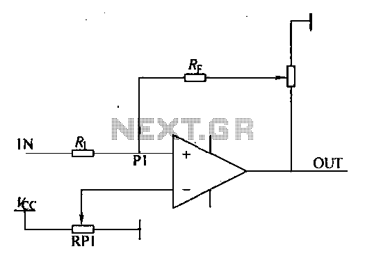
Loop comparator circuit
Environmental interference can affect the transfer switching, leading to the production of burrs in confidence disgrace. The switch position signal will control the computer system with the reliability of lanthanum burrs. The work has some impact. Glitches are typically addressed...

lowvoltage ac voltmeter
The primary component of this circuit is an operational amplifier (such as the 741 or 351), configured as an amplifier with a feedback circuit that consists of a diode bridge full-wave rectifier. An ammeter is connected to the rectifier circuit,...

cut the feed forward in the miller compensation with voltage buffer
An internally compensated operational amplifier has been fabricated using n-channel Al-gate MOS technology, utilizing only enhancement mode devices. The circuit is designed to ensure that its performance remains insensitive to process parameters. The input stage consists of a source-coupled differential...

Four-channel-comparator
When operated as an open loop without compensation, the HA-2400 functions as a comparator with four selectable input channels. The clamping network at the compensation pin limits the output voltage, enabling DTL or TTL digital circuits to be driven with...
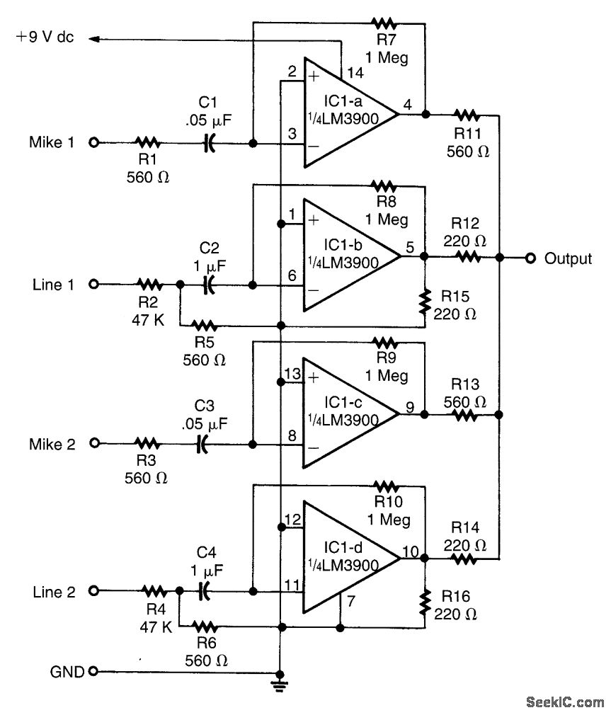
AUDIO MIXER
This circuit is designed around an LM3900 quad operational amplifier, which combines two line inputs and two microphone inputs, summing them at the output terminal. Resistors R7 through R10 can be adjusted to vary the gain, approximately +23 dB.
The circuit...

X10 operational amplifier
The amplifier is 3 dB down at 100 kHz and has a slew rate of 0.02 V/µs.
The amplifier's performance characteristics indicate that it experiences a 3 dB attenuation at a frequency of 100 kHz. This specification suggests that at this...

Cosine wave Oscillator
This circuit is designed to output both a sine wave and a cosine wave. The design utilizes an operational amplifier, with the output frequency determined by component values set to 1Hz. The first operational amplifier generates a 1Hz sine wave,...

Square transform circuit diagram
At the input of the operational amplifier, a resistor-diode network can be constructed to create a square-law function conversion circuit. This resistor-diode network acts as a voltage divider, where the input voltage variations lead to different partial pressures. The three...