


LF356 Wide Range Current-To-Voltage Converter
#current-to-voltage converter
#LF356
#op-amp
#signal conversion
#wide range
#analog circuits
#precision
#sensor interface
#low noise
#high impedance

Description: A current-to-voltage converter circuit can be constructed using a single resistor. This design is straightforward, as any current flowing through a resistor will naturally generate a voltage.
A current-to-voltage converter, also known as a transimpedance amplifier, is primarily utilized to convert an input current signal into a corresponding output voltage signal. This type of circuit is particularly useful in applications such as photodetectors, where the output is a current generated by light exposure, and it needs to be converted into a voltage for further processing.
In its simplest form, the circuit consists of a resistor (R) connected to the output terminal. When an input current (I_in) flows through the resistor, Ohm's Law (V = I × R) dictates that a voltage (V_out) will be developed across the resistor. The output voltage can be expressed as V_out = I_in × R, where V_out is the voltage across the resistor, I_in is the input current, and R is the resistance value.
The choice of resistor value is critical in determining the sensitivity and range of the circuit. A higher resistance will produce a larger output voltage for a given input current, but may also increase noise and reduce bandwidth. Conversely, a lower resistance will yield a smaller output voltage but may provide better performance in terms of speed and noise immunity.
For practical applications, additional components such as operational amplifiers (op-amps) may be integrated into the design to improve performance characteristics, such as input impedance, gain stability, and noise reduction. In these configurations, the op-amp can be used to buffer the output, thereby isolating the load from the current-to-voltage conversion stage and allowing for more precise voltage readings.
Overall, the current-to-voltage converter is a fundamental circuit that serves as a building block in various electronic systems, enabling the effective translation of current signals into voltage signals for further analysis or processing.Current to voltage converter circuit can be made using a single resistor, it is very simple since any current will naturally develop a voltage when flow through.
A current-to-voltage converter, also known as a transimpedance amplifier, is primarily utilized to convert an input current signal into a corresponding output voltage signal. This type of circuit is particularly useful in applications such as photodetectors, where the output is a current generated by light exposure, and it needs to be converted into a voltage for further processing.
In its simplest form, the circuit consists of a resistor (R) connected to the output terminal. When an input current (I_in) flows through the resistor, Ohm's Law (V = I × R) dictates that a voltage (V_out) will be developed across the resistor. The output voltage can be expressed as V_out = I_in × R, where V_out is the voltage across the resistor, I_in is the input current, and R is the resistance value.
The choice of resistor value is critical in determining the sensitivity and range of the circuit. A higher resistance will produce a larger output voltage for a given input current, but may also increase noise and reduce bandwidth. Conversely, a lower resistance will yield a smaller output voltage but may provide better performance in terms of speed and noise immunity.
For practical applications, additional components such as operational amplifiers (op-amps) may be integrated into the design to improve performance characteristics, such as input impedance, gain stability, and noise reduction. In these configurations, the op-amp can be used to buffer the output, thereby isolating the load from the current-to-voltage conversion stage and allowing for more precise voltage readings.
Overall, the current-to-voltage converter is a fundamental circuit that serves as a building block in various electronic systems, enabling the effective translation of current signals into voltage signals for further analysis or processing.Current to voltage converter circuit can be made using a single resistor, it is very simple since any current will naturally develop a voltage when flow through.

OpAmp based Voltage Translator Ciruit for ADC of Micro-controller
All naturally occurring phenomena such as sound, temperature, and pressure are analog in nature. To enable a microcontroller to read analog signals for the analog-to-digital conversion process using a built-in analog-to-digital converter (ADC), it is essential to condition the analog...

Combined Light-/Dark-Activated Switch Circuit
Two operational amplifiers are utilized in a bridge circuit configuration to detect high and low light levels. Potentiometer R2 adjusts the dark level, while resistor R1 controls the light level. Resistor R3 is configured so that approximately 1A of the...

low noise oscillator design
The overall performance of any RF circuit regarding its phase noise and spectral purity depends significantly on the frequency-generating circuitry, commonly an oscillator. Low noise oscillators with high spectral purity are neither mysterious nor magical. Many individuals perceive the design...

Capacitor in parallel with resistor on xoscope amplifier schematic
For capacitor C3, a 100pF capacitor is placed across resistor R2. The circuit functions similarly to previous configurations, although no explanation is provided. The purpose of this component may be self-evident to experienced users, but it may not be clear...
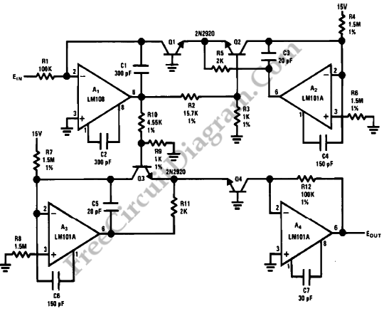
Power Function Circuit
It is possible to easily generate various non-linear functions such as X^(1/2), X^2, X^3, 1/X, XY, and X/Y using logarithms. In this context, division is transformed into subtraction, while multiplication is converted into addition.
The application of logarithmic properties in electronic...

op amp IR Demodulator Design
Designing an infrared (IR) demodulator circuit to replace the one shown in this question. The goal is to demodulate a simple IR signal modulated at 32.678 kHz, with the requirement of detecting the presence of the signal without packet decoding....
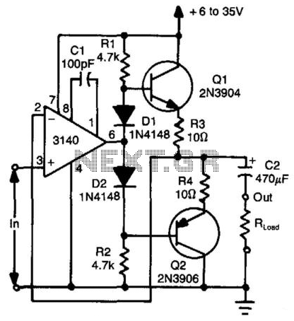
Bidirectional Compound Op Amp
Using two transistors (Q1 and Q2), a bidirectional operational amplifier can source or sink up to 50 mA. Diodes D1 and D2 provide biasing for Q1 to eliminate "dead-zone" effects.
The described circuit utilizes two transistors, Q1 and Q2, configured to...

Continuity Checker
U1 is an operational amplifier used as a comparator. When the test probes are shorted together, resistors R1 and R2 bias the non-inverting input to half the supply voltage. The inverting input is biased by a voltage divider that consists...

Home Built Laser Projector
This document outlines the servo amplifier and its circuit diagram. It describes a straightforward operational amplifier circuit that integrates both a power amplifier and a small signal amplifier on the same board. Care must be taken to avoid unintended coupling...