


Transistor Checker Circuit
#transistor checker
#741 op amp
#voltage follower
#meter calibration
#voltage measurement
#potentiometer
#circuit testing
#electronics diagnostic

Description: The circuit is designed around a 741 general-purpose operational amplifier (op amp) configured as a voltage follower, providing a voltage gain of one. The output from the 741 is utilized to drive a 50-meter movement. Potentiometer R7 is employed to zero the meter, while R6 is responsible for setting the meter's full-scale reading. Calibration of the meter is straightforward: with no input signal applied, R6 should be set to the mid-position, followed by adjusting R7 to zero the meter. After this initial setup, a positive 1-Vdc voltage is applied to the input, and R6 is adjusted to achieve a full-scale reading. The voltmeter can also be calibrated to read both positive and negative voltages by adjusting R7 to center the scale at the meter's zero position and ensure a positive 1-V reading at the full-scale position.
The circuit utilizes a 741 operational amplifier, which is a widely used component in analog electronics due to its versatility and reliability. The op amp is configured as a voltage follower, meaning that the output voltage directly follows the input voltage, resulting in no amplification but providing high input impedance and low output impedance. This characteristic is particularly useful in applications where signal buffering is required.
The use of a 50-meter movement indicates that the circuit is intended for applications requiring a visual representation of voltage levels, such as in analog voltmeters. The potentiometer R7 allows for fine-tuning of the zero point on the meter, ensuring accurate readings across the entire scale. Potentiometer R6 is critical for setting the full-scale reading, allowing the user to calibrate the meter to the desired maximum voltage range.
Calibration procedures are essential for ensuring the accuracy of the voltmeter. The initial step of setting R6 to the mid-position with no input helps establish a baseline for the meter's operation. Adjusting R7 to zero the meter ensures that the device can accurately measure voltages around the zero point, which is crucial for applications involving both positive and negative voltages. By applying a known voltage of 1 Vdc and adjusting R6 accordingly, the user can ensure that the meter provides accurate full-scale readings, thereby enhancing the reliability of the measurements taken.
The ability to adjust the voltmeter to read both positive and negative voltages expands its functionality, making it suitable for a wider range of applications. This dual capability is achieved through careful adjustment of R7, which centers the scale and allows for accurate readings regardless of the polarity of the input voltage. Overall, the described circuit is an effective and efficient solution for voltage measurement tasks in various electronic applications. The circuit is built around a 741 general-purpose op amp that is configured as a voltage follower; with the components shown, the op amp has a voltage gain of one. The output of the 741 is used to drive a 50- meter movement. Potentiometer R7 is used to zero the meter and R6 sets the meter`s full-scale reading, Calibrating the meter is a snap.
With no input applied to the circuit, set R6 to mid-position and adjust R7 to zero the meter. Once that is done, apply a positive 1-Vdc voltage to the input and adjust R6 for a full-scale reading. The voltmeter can be adjusted to read both positive and negative voltages by adjusting R7 for a center scale reading at the meter`s zero position and a positive 1- V reading at the meter`s full-scale position.
The circuit utilizes a 741 operational amplifier, which is a widely used component in analog electronics due to its versatility and reliability. The op amp is configured as a voltage follower, meaning that the output voltage directly follows the input voltage, resulting in no amplification but providing high input impedance and low output impedance. This characteristic is particularly useful in applications where signal buffering is required.
The use of a 50-meter movement indicates that the circuit is intended for applications requiring a visual representation of voltage levels, such as in analog voltmeters. The potentiometer R7 allows for fine-tuning of the zero point on the meter, ensuring accurate readings across the entire scale. Potentiometer R6 is critical for setting the full-scale reading, allowing the user to calibrate the meter to the desired maximum voltage range.
Calibration procedures are essential for ensuring the accuracy of the voltmeter. The initial step of setting R6 to the mid-position with no input helps establish a baseline for the meter's operation. Adjusting R7 to zero the meter ensures that the device can accurately measure voltages around the zero point, which is crucial for applications involving both positive and negative voltages. By applying a known voltage of 1 Vdc and adjusting R6 accordingly, the user can ensure that the meter provides accurate full-scale readings, thereby enhancing the reliability of the measurements taken.
The ability to adjust the voltmeter to read both positive and negative voltages expands its functionality, making it suitable for a wider range of applications. This dual capability is achieved through careful adjustment of R7, which centers the scale and allows for accurate readings regardless of the polarity of the input voltage. Overall, the described circuit is an effective and efficient solution for voltage measurement tasks in various electronic applications. The circuit is built around a 741 general-purpose op amp that is configured as a voltage follower; with the components shown, the op amp has a voltage gain of one. The output of the 741 is used to drive a 50- meter movement. Potentiometer R7 is used to zero the meter and R6 sets the meter`s full-scale reading, Calibrating the meter is a snap.
With no input applied to the circuit, set R6 to mid-position and adjust R7 to zero the meter. Once that is done, apply a positive 1-Vdc voltage to the input and adjust R6 for a full-scale reading. The voltmeter can be adjusted to read both positive and negative voltages by adjusting R7 for a center scale reading at the meter`s zero position and a positive 1- V reading at the meter`s full-scale position.
Voltage follower
It is important to note that not all transistors have the same terminal designations or pinouts, despite having similar physical appearances. This distinction will influence how transistors are interconnected and connected to other components, making it essential to consult the...

Transistor Checker with 555
This simple circuit has helped me out on many occasions. It is able to check transistors, in the circuit, down to 40 ohms across the collector-base or base-emitter junctions. It can also check the output power transistors on amplifier circuits....

Coulomb meter
Another cause of voltage drift is the input current of IC1, which slowly charges capacitor C1. This effect is particularly noticeable when the output voltage is approximately 0 volts.
The circuit in question involves an integrated circuit (IC1) whose input current...

Battery status indicator circuit diagram
The 741 operational amplifier can function as a voltage comparator. It features a non-inverting input and a Zener-controlled voltage source, with a reference voltage set at 5.1V. Resistor R2 is used to adjust the in-phase input voltage to half of...

potentiometer Making an adjustable resistance
This part of the circuit is isolated from any other component, except for the 5V and ground connections. It includes LEDs and a shift register, which may not interact significantly. The LDR (Light Dependent Resistor) is utilized solely as a...

music circuit
This circuit allows for the adjustment of resistance using a potentiometer and the adjustment of capacitance by opening or closing switches. By manipulating the configuration of these switches, various combinations can be achieved to obtain different effective capacitance values. It...

WIEN BRIDGE OSCILLATOR CIRCUIT
A 741 operational amplifier is configured within a Wien-bridge audio sine-wave oscillator circuit. The components C1, C2, R1, and R2 are responsible for determining the operating frequency of the circuit. By utilizing NPO capacitors and metal-film resistors, the oscillator achieves...

The Measurements for MIT 3DL1 Run
The chips that are classified as "working well" produce approximately 300 mV when exposed to a laser pointer and between 40 to 80 mV when illuminated by LED light. Voltages around 100 mV were recorded in a sunlit environment, while...
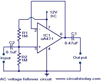
Voltage follower circuit
An AC-coupled unity gain voltage follower operating on a single supply is illustrated. The voltage divider network consisting of resistors R1 and R2 provides a DC voltage equal to half the supply voltage to the non-inverting input of the 741...