


Voltage/current conversion circuit composed of LM301
#LM301
#voltage to current converter
#operational amplifier
#current source
#signal conversion
#bias current
#circuit design
#electronics
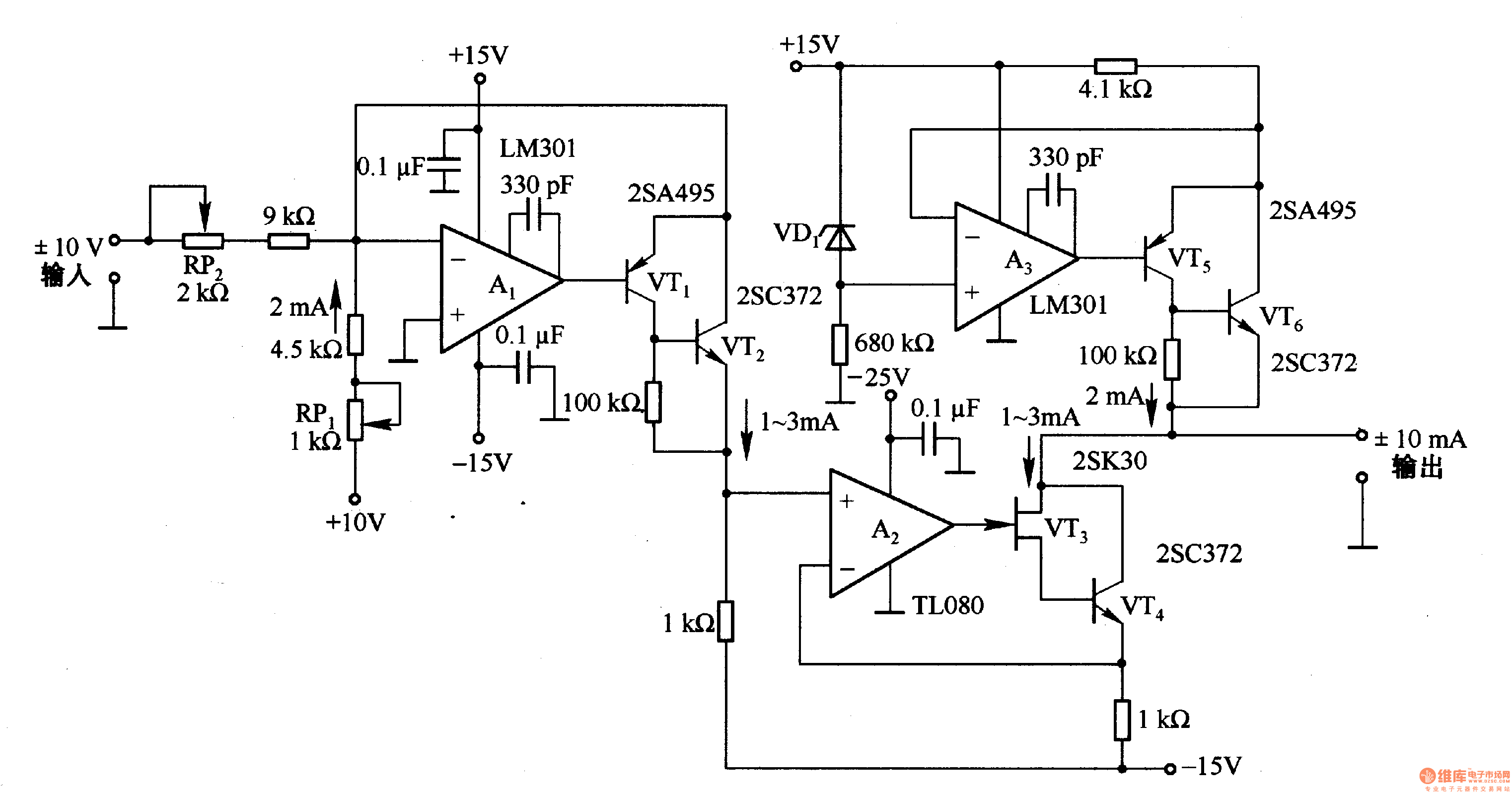
Description: This circuit is designed for voltage-to-current conversion, specifically transforming a ±10V input voltage into a ±1mA output current. The conversion process is facilitated by operational amplifier A1 and transistors VT1 and VT2, which are responsible for altering the current direction. A bias current of 2mA is applied at the input; thus, when the input voltage is 0V, a current of 2mA flows through the circuit. Additionally, the output stage incorporates a 2mA constant current source.
The voltage-to-current conversion circuit operates by utilizing an operational amplifier (A1) configured in a feedback loop to maintain a precise output current that corresponds to the input voltage. The transistors (VT1 and VT2) function as switches that control the direction of the output current, allowing for both positive and negative current outputs depending on the input voltage polarity.
The circuit's design includes a biasing mechanism that ensures a constant 2mA current flows when the input voltage is at 0V. This feature is essential for applications that require a baseline current level for proper operation. The inclusion of a constant current source at the output further stabilizes the output current, ensuring that it remains at 2mA regardless of variations in load resistance.
In practical applications, this circuit can be utilized in sensor interfacing, where voltage signals from sensors need to be converted into current signals for further processing or transmission. The precision of the operational amplifier and the current control provided by the transistors make this circuit suitable for high-performance requirements in industrial and scientific instrumentation. Overall, the design is robust and reliable, providing a straightforward solution for voltage-to-current conversion tasks.It is the conversion circuit, which can transform ±10V voltage into ±lmA, and the input voltage is changed into current by the A1 and VTl, VT2, and it is used to change the current direction. The input end is added 2mA bias current, when the input voltage is OV, there is 2mA current flowing; the output termination is added 2mA constant current source circu..
The voltage-to-current conversion circuit operates by utilizing an operational amplifier (A1) configured in a feedback loop to maintain a precise output current that corresponds to the input voltage. The transistors (VT1 and VT2) function as switches that control the direction of the output current, allowing for both positive and negative current outputs depending on the input voltage polarity.
The circuit's design includes a biasing mechanism that ensures a constant 2mA current flows when the input voltage is at 0V. This feature is essential for applications that require a baseline current level for proper operation. The inclusion of a constant current source at the output further stabilizes the output current, ensuring that it remains at 2mA regardless of variations in load resistance.
In practical applications, this circuit can be utilized in sensor interfacing, where voltage signals from sensors need to be converted into current signals for further processing or transmission. The precision of the operational amplifier and the current control provided by the transistors make this circuit suitable for high-performance requirements in industrial and scientific instrumentation. Overall, the design is robust and reliable, providing a straightforward solution for voltage-to-current conversion tasks.It is the conversion circuit, which can transform ±10V voltage into ±lmA, and the input voltage is changed into current by the A1 and VTl, VT2, and it is used to change the current direction. The input end is added 2mA bias current, when the input voltage is OV, there is 2mA current flowing; the output termination is added 2mA constant current source circu..

XTR112 114 bridge input current excitation circuit diagram
The two current sources within the chip (1 foot and 14 feet out) provide excitation. The output of each current source is 0.2 mA (XTR114) or 0.5 A (XTR112). The common mode input voltage is adjustable, ranging from 1.25 to...

X10 operational amplifier
The amplifier is 3 dB down at 100 kHz and has a slew rate of 0.02 V/µs.
The amplifier's performance characteristics indicate that it experiences a 3 dB attenuation at a frequency of 100 kHz. This specification suggests that at this...

Precision current sink sourcel
An operational amplifier circuit can provide a constant voltage source with a high amplification factor and substantial load current. Even with significant variations in circuit parameters, the output voltage maintains high precision. The output current limit is managed by transistors...

Bipolar-reference-source
This current source provides continuous control over the magnitude and polarity of its amplifier gain, requiring only a single voltage reference. The circuit comprises a voltage-amplifier circuit (A1) with a gain-setting resistor (Rs) and a bootstrap-follower amplifier (A2). The bootstrapping...

Current source
This precision current source features output current ranges from 10 µA to 10 mA, with an output compliance of 30 V to -5 V. The output current is fully adjustable within each range using a calibrated ten-turn potentiometer. An error...

Fast Voltage-Driven Current Source
The current source in the diagram reacts very quickly to changes in the input signal and may be utilized in specific measurements. The differential amplifier IC1 ensures that the voltage across R2 is equal to the input voltage, represented by...

TA-1500 fever amplifier circuit
Only the R channel is shown, with the original reference PCB label. Figure (a) illustrates the front tone circuit, which consists of a common negative feedback operational amplifier in an RC circuit configuration. The microphone signal is amplified by VTz,...
Current / voltage conversion circuit composed of LM301
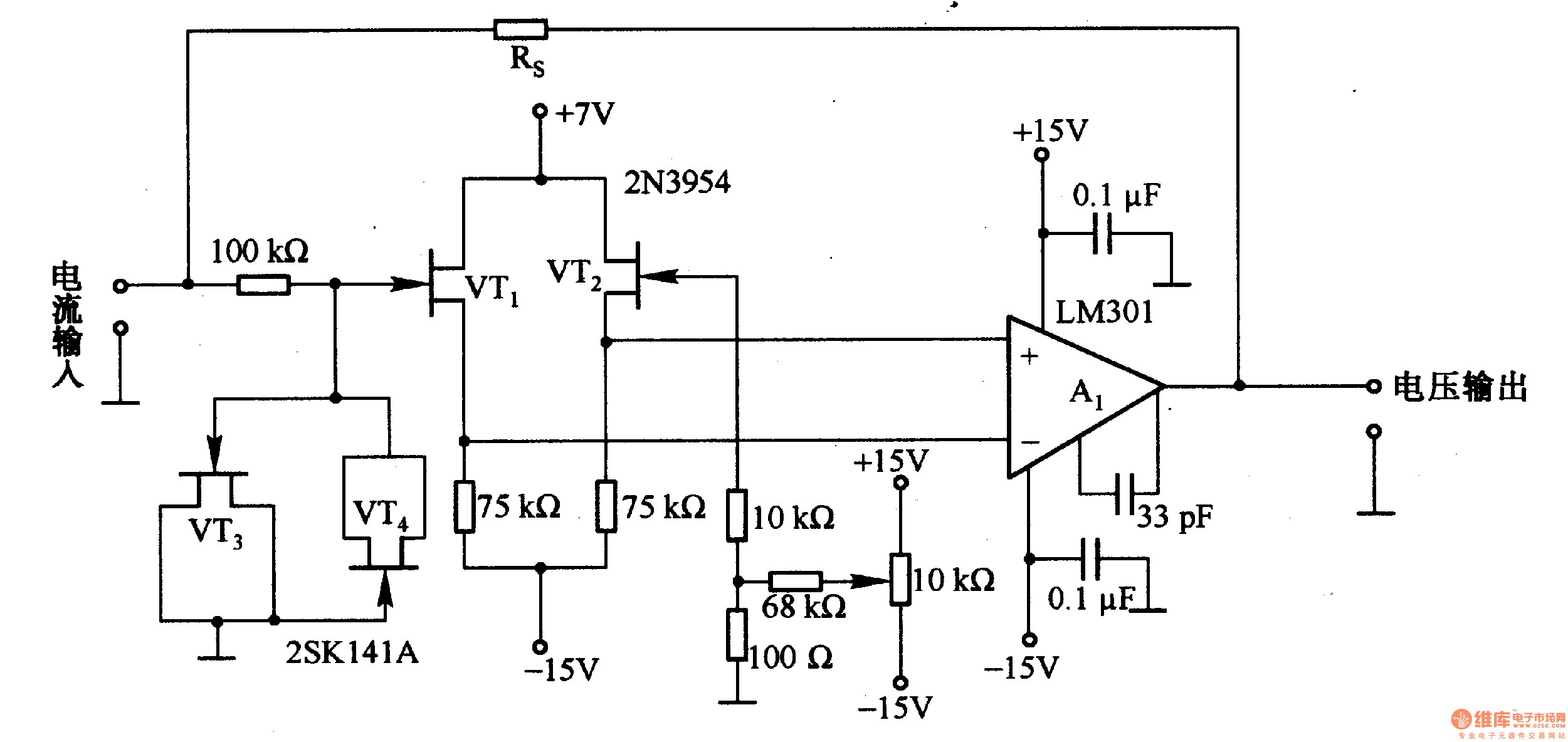
This is a low-input impedance conversion circuit with the reference resistor RS connected to the amplifier's feedback loop, resulting in an input impedance close to zero. The input current flows into the output end of the operational amplifier (Op-Amp) through...

Operational-amplifiers
This is a single gain-of-100 amplifier with a gain-bandwidth product of 20 MHz. The primary limitation in performance is the low slew rate of 0.3 V/μs imposed by the charging of Ccomp. The effects of slew rate and compensation are...