


Current / voltage conversion circuit composed of LM301
#LM301
#current-to-voltage
#low-input impedance
#feedback loop
#op amp
#conversion circuit
#resistor
#amplifier
#output current
#signal conversion
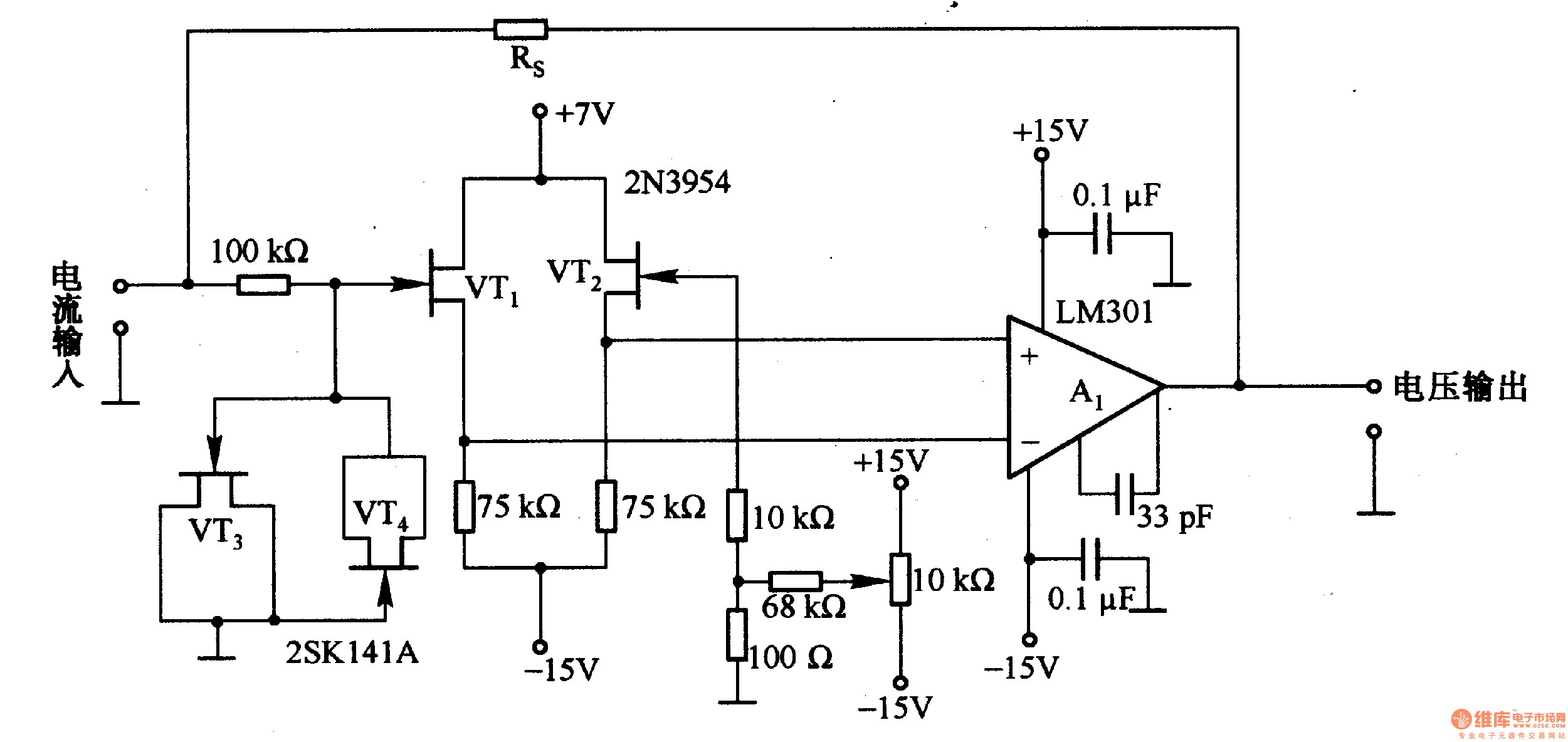
Description: This is a low-input impedance conversion circuit with the reference resistor RS connected to the amplifier's feedback loop, resulting in an input impedance close to zero. The input current flows into the output end of the operational amplifier (Op-Amp) through RS. The maximum switching current is determined by the output current of the Op-Amp, with the circuit's maximum switching current being 10 mA.
This low-input impedance conversion circuit is designed to efficiently handle signals with minimal loading effect on the source. By connecting the reference resistor RS in the feedback loop of the Op-Amp, the circuit achieves a very low input impedance, which is advantageous in applications where signal integrity is critical, such as in sensor interfacing or signal conditioning.
The operational amplifier utilized in this design is configured to provide a high gain, which is essential for amplifying weak signals. The input current, which is the signal of interest, is directed through the reference resistor RS. This configuration ensures that the Op-Amp can drive the output without significant voltage drop across the input terminals, maintaining the integrity of the incoming signal.
The maximum switching current of 10 mA is a critical parameter for the circuit's performance. It is determined by the output current capabilities of the Op-Amp, which must be chosen based on the specific application requirements. The Op-Amp must be capable of sustaining this current without distortion or degradation of the signal.
In practical applications, this circuit can be employed in various fields such as biomedical instrumentation, where low-level signals from sensors need to be amplified without introducing noise or loading effects. The design considerations must include the choice of the Op-Amp, the value of the reference resistor RS, and the power supply requirements to ensure reliable operation within the specified current limits.This is a low-input impedance conversion circuit with reference resistor RS being connected to the amplifier`s feedback loop and input impedance in approximately zero, and the input current flows into Al`s output end through Rs. The maximum switching current is decided by the op amp output current, and the maximum switching current of circuit is lOmA.
When i..
This low-input impedance conversion circuit is designed to efficiently handle signals with minimal loading effect on the source. By connecting the reference resistor RS in the feedback loop of the Op-Amp, the circuit achieves a very low input impedance, which is advantageous in applications where signal integrity is critical, such as in sensor interfacing or signal conditioning.
The operational amplifier utilized in this design is configured to provide a high gain, which is essential for amplifying weak signals. The input current, which is the signal of interest, is directed through the reference resistor RS. This configuration ensures that the Op-Amp can drive the output without significant voltage drop across the input terminals, maintaining the integrity of the incoming signal.
The maximum switching current of 10 mA is a critical parameter for the circuit's performance. It is determined by the output current capabilities of the Op-Amp, which must be chosen based on the specific application requirements. The Op-Amp must be capable of sustaining this current without distortion or degradation of the signal.
In practical applications, this circuit can be employed in various fields such as biomedical instrumentation, where low-level signals from sensors need to be amplified without introducing noise or loading effects. The design considerations must include the choice of the Op-Amp, the value of the reference resistor RS, and the power supply requirements to ensure reliable operation within the specified current limits.This is a low-input impedance conversion circuit with reference resistor RS being connected to the amplifier`s feedback loop and input impedance in approximately zero, and the input current flows into Al`s output end through Rs. The maximum switching current is decided by the op amp output current, and the maximum switching current of circuit is lOmA.
When i..

Op Amp And Two JFETs Form A Voltage-Controlled Amplifier
A simple linear voltage-controlled amplifier can be constructed with one operational amplifier (op amp) and two junction field-effect transistors (JFETs). This amplifier can achieve an 80-dB dynamic control range with less than ±0.2% linearity error for 0 V.
The described circuit...

Current-to-voltage converter
The converter features eight decades of current range. The circuit is intended to be used with the 200 mV range of a DVM.
The described converter circuit is designed to accommodate a wide range of current measurements, spanning eight decades. This...

THERMOMETER ADAPTER
A simple operational amplifier and silicon diode form the core of a temperature-to-voltage converter, allowing the use of a standard voltmeter—either analog or digital—to measure temperature. User adjustments enable readings of either 10 mV or 100 mV to correspond to...

amplifier timer
This circuit deactivates an amplifier or any other device when a low-level audio signal at its input is absent for at least 15 minutes. By pressing P1, the device is powered on, allowing any appliance connected to SK1 to operate....
DC-Coupled Audio Amplifier
Designs for audio amplifiers with DC coupling to the load are not commonly seen today, despite their clear benefits. One advantage...
Audio amplifiers utilizing DC coupling to the load present several notable advantages in specific applications. DC coupling allows for a...

circuit power audio amplifier with
This circuit is a complete application for a 2.1 amplifier system, featuring two satellite speakers for TDA and one subwoofer. It is commonly used in commercial applications to enhance the audio output of computers using a stereo amplifier along with...

Triangular wave generator using Op Amp 741 circuit working and simulated output waveform
An operational amplifier-based triangular waveform generator is a simple circuit that is widely used in function generators. This circuit utilizes the 741 operational amplifier to create a triangular wave generator. The output waveform of an integrator will be triangular when...

Power Supply for Amlifiers [B]
Proposed power supply for amplifier 100W v-mosfet is what appears in the above form. It has separated supply for the various stages of supply, stage for power, stage for control, supply for preamplifier and for stage of protection. Whoever wants...
Voltage/current conversion circuit composed of LM301
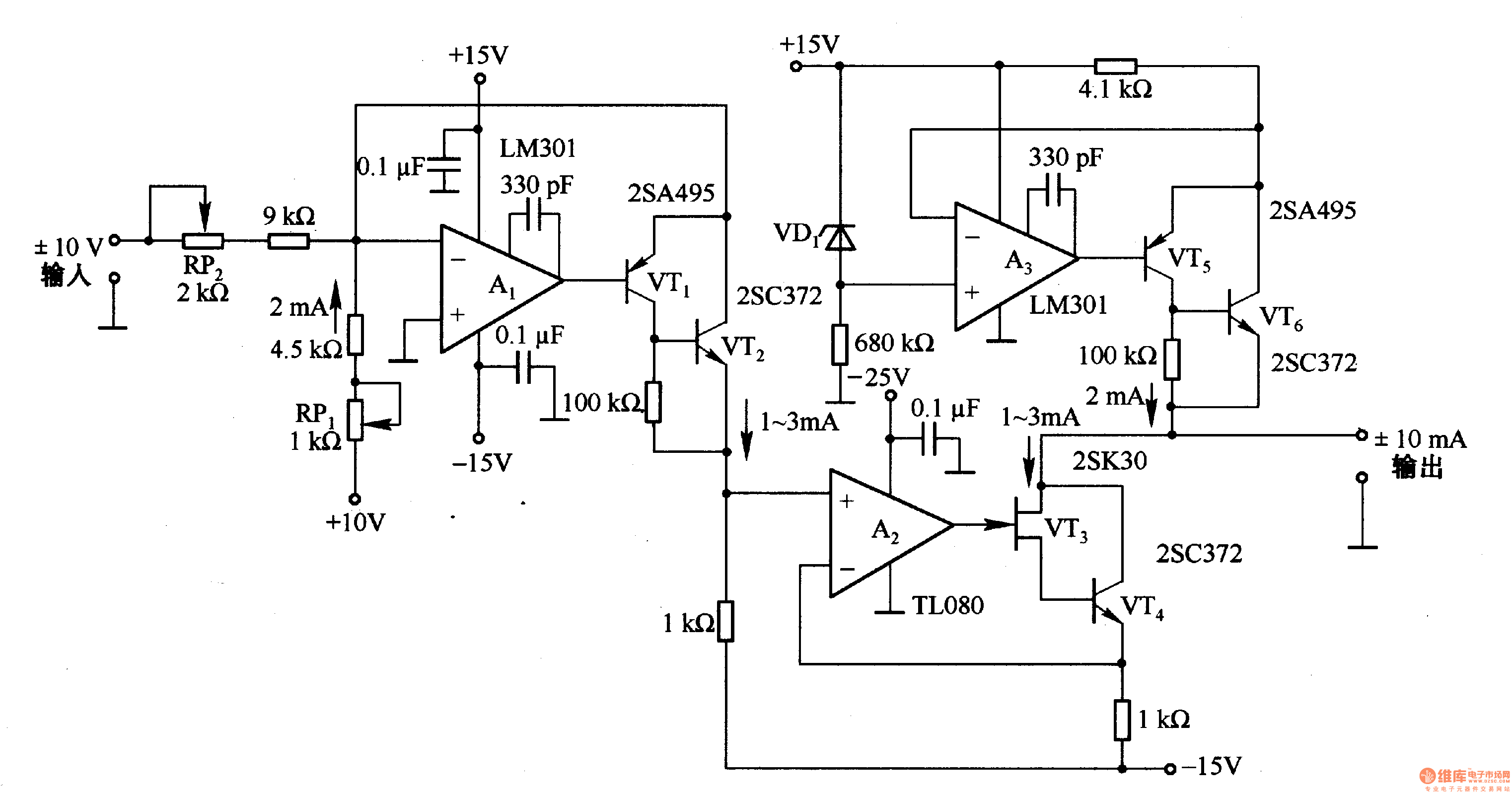
This circuit is designed for voltage-to-current conversion, specifically transforming a ±10V input voltage into a ±1mA output current. The conversion process is facilitated by operational amplifier A1 and transistors VT1 and VT2, which are responsible for altering the current direction....