


Oscilloscope-calibrator
#NE555
#astable
#frequency calibration
#oscilloscope
#1 kHz
#potentiometer
#time-base generator
#frequency counter

Description: The calibrator can be utilized to verify the accuracy of a time-base generator and to calibrate the input level of amplifiers. It consists of an NE555 timer configured in astable mode. The oscillator frequency is precisely set to 1 kHz by adjusting potentiometer P1 while the output at pin 3 is monitored against a known frequency standard or frequency counter. Additionally, the output level is monitored from the center arm of potentiometer P2 to ground using a standard instrument. P2 is adjusted to achieve a 1 V peak-to-peak output at the calibrator output terminal. During operation, the calibrator output terminal generates a 1-kHz square wave signal at 1 V peak-to-peak with an approximate 50% duty cycle. For long-term frequency stability of the oscillator, capacitor C1 should be a low-leakage mylar capacitor.
The electronic circuit described employs the NE555 timer IC, a versatile component widely used for generating precise timing and oscillation signals. In the astable configuration, the NE555 operates as a free-running oscillator, producing a continuous square wave output. The frequency of oscillation is determined by the resistors and capacitor connected to the timer. In this case, potentiometer P1 is used to fine-tune the frequency to exactly 1 kHz, which is critical for applications requiring precise timing.
The output signal from pin 3 of the NE555 is a square wave with a frequency of 1 kHz and a duty cycle close to 50%. This means that the signal remains high for approximately half of the period and low for the other half, making it suitable for testing various electronic devices that require a stable timing reference.
Potentiometer P2 serves a dual purpose: it allows for monitoring the output level of the calibrator and provides an adjustable output voltage. By connecting the center arm of P2 to ground and using a standard measuring instrument, the output can be calibrated to a precise 1 V peak-to-peak. This feature is particularly useful for ensuring that amplifiers or other signal processing components receive a known input level, facilitating accurate performance testing.
Capacitor C1 plays a crucial role in maintaining the stability of the oscillator's frequency over time. A low-leakage mylar capacitor is recommended to minimize any drift in the frequency that could arise from leakage currents, ensuring that the calibrator remains accurate during prolonged use.
Overall, this calibrator circuit is a valuable tool for electronics testing and calibration, providing a reliable means to ensure the accuracy of time-base generators and amplifier input levels. Its design emphasizes precision and stability, making it suitable for various applications in electronics laboratories and testing environments.The calibrator can be used to check the accuracy of a time-base generator, as well as to calibrate the input level of amplifiers. The calibrator consists of an NE555 connected in the astable mode. The oscillator is set to exactly 1 kHz by adjusting potentiometer P1 while tbe output at pin 3 is being monitored against a known frequency standard or frequency counter.
The output level, likewise, is monitored from potentiometer P2"s center arm to ground with a standard instrument. P2 is adjusted for 1 V pk-pk at tbe calibrator output terminal. During operation, tbe calibrator output terminal will produce a 1-kHz, square-wave signal at 1 V pk-pk with about 50% duty cycle.
For long-term oscillator frequency stability, Cl should be a lowleakage mylar capacitor.
The electronic circuit described employs the NE555 timer IC, a versatile component widely used for generating precise timing and oscillation signals. In the astable configuration, the NE555 operates as a free-running oscillator, producing a continuous square wave output. The frequency of oscillation is determined by the resistors and capacitor connected to the timer. In this case, potentiometer P1 is used to fine-tune the frequency to exactly 1 kHz, which is critical for applications requiring precise timing.
The output signal from pin 3 of the NE555 is a square wave with a frequency of 1 kHz and a duty cycle close to 50%. This means that the signal remains high for approximately half of the period and low for the other half, making it suitable for testing various electronic devices that require a stable timing reference.
Potentiometer P2 serves a dual purpose: it allows for monitoring the output level of the calibrator and provides an adjustable output voltage. By connecting the center arm of P2 to ground and using a standard measuring instrument, the output can be calibrated to a precise 1 V peak-to-peak. This feature is particularly useful for ensuring that amplifiers or other signal processing components receive a known input level, facilitating accurate performance testing.
Capacitor C1 plays a crucial role in maintaining the stability of the oscillator's frequency over time. A low-leakage mylar capacitor is recommended to minimize any drift in the frequency that could arise from leakage currents, ensuring that the calibrator remains accurate during prolonged use.
Overall, this calibrator circuit is a valuable tool for electronics testing and calibration, providing a reliable means to ensure the accuracy of time-base generators and amplifier input levels. Its design emphasizes precision and stability, making it suitable for various applications in electronics laboratories and testing environments.The calibrator can be used to check the accuracy of a time-base generator, as well as to calibrate the input level of amplifiers. The calibrator consists of an NE555 connected in the astable mode. The oscillator is set to exactly 1 kHz by adjusting potentiometer P1 while tbe output at pin 3 is being monitored against a known frequency standard or frequency counter.
The output level, likewise, is monitored from potentiometer P2"s center arm to ground with a standard instrument. P2 is adjusted for 1 V pk-pk at tbe calibrator output terminal. During operation, tbe calibrator output terminal will produce a 1-kHz, square-wave signal at 1 V pk-pk with about 50% duty cycle.
For long-term oscillator frequency stability, Cl should be a lowleakage mylar capacitor.
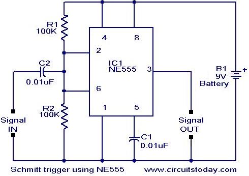
Scmitt Trigger circuit using NE 555
In addition to its timing functions, the two comparators of the 555 timer can be utilized independently for various applications. One such application is a Schmitt Trigger. The inputs of the two comparators (pin 2 and pin 6) are connected...

on off relay circuit automatic
The circuit operates continuously, turning on and off. It utilizes the widely recognized NE555 timer IC, known for its versatility in various electronic applications. In this configuration, the IC is set up as an astable multivibrator. A 12-volt relay is...

USB Live Oscilloscope: Main Board
The two input boards (ADCV or digital) are connected to AD_CTL1, AD_DATA1, AD_SUP5V_1, and AD_SUP3V3_1 for the first board, with the second board using the same connections but with a suffix of 2. To transfer sampling data, the 16 digital...

Astable oscillator
Before power is applied, the input and output are at ground potential, and capacitor C is discharged. Upon power-on, the output transitions to high (Vdd), and capacitor C charges through resistor R until a specified voltage (V) is reached; thereafter,...
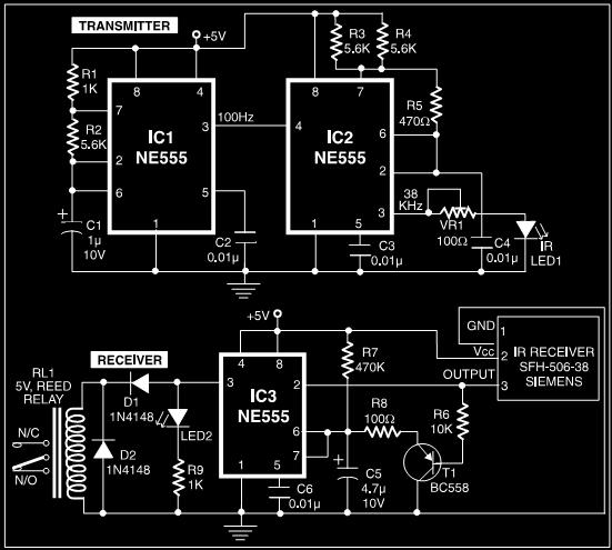
Proximity Detector Circuit Using NE555 PCB
This post discusses a proximity detector circuit primarily utilizing the NE555 integrated circuit (IC). The circuit is designed for burglar alarms based on beam interruption, with the advantage that the transmitter and receiver are contained within the same enclosure, eliminating...

Interface Circuit for PC Soundcard Oscilloscope
For simple electronic circuits, it may be sufficient to gain qualitative insights on dedicated electrical signals. This interface circuitry allows the line-in input of a standard PC sound card to be utilized as a 2-channel oscilloscope. Although this setup does...

Sawtooth Wave Generator
A sawtooth wave generator utilizing the NE555 timer and the uA741 operational amplifier. The NE555 is configured as a square wave generator, while the uA741 is set up as an integrator. The circuit diagram and working theory are included.
The sawtooth...

Mains Frequency Monitor circuit and explanation
This is a simple frequency counter designed to monitor the 240VAC mains supply. It has a frequency range of 0-999Hz, making it suitable for use with 400Hz equipment as well. Standard TTL/CMOS logic is utilized for the counters and display...

A house automatically fill light circuit
The circuit consists of three parts: a light control section, a time control section, and a power supply section. The light control section utilizes a photoresistor (Rg) and a variable resistor (RP) to detect light levels. During the day, when...