


ultrasonic transmitter circuit
#555 timer
#ultrasonic
#transducer
#astable multivibrator
#40 kHz
#signal generator
#frequency
#electronic oscillator
#timing circuit

Description: The circuit utilizes a 555 timer integrated circuit (IC) configured as an astable multivibrator, which generates a continuous signal at a specific frequency as long as its reset pin (pin 4) is held high. The ultrasonic transducer employed in this circuit is designed to optimally vibrate at approximately 40 kHz. Consequently, the resistor and capacitor values were selected to ensure that the 555 timer outputs a signal with a frequency near 40 kHz. This output is amplified by transistor Q1, which drives the ultrasonic transducer. The transducer subsequently vibrates at 40 kHz, producing ultrasonic sound waves at that frequency. When paired with a compatible ultrasonic receiver, this simple transmitter can function as a proximity sensor, such as one that aids a robot in avoiding obstacles. For effective operation in this capacity, the transmitter and receiver transducers must be aligned so that the receiver captures only the echoes of the transmitted signal and not the direct transmitted signal itself.
The circuit design begins with the 555 timer IC, which is a versatile component widely used for generating precise timing and oscillation. In the astable configuration, the 555 timer operates without any external triggering, continuously switching its output between high and low states. The frequency of oscillation is determined by the external resistor-capacitor (RC) network connected to the timer. The values of these resistors (R1 and R2) and the capacitor (C1) are calculated using the formula:
\[ f = \frac{1.44}{(R1 + 2R2) \times C1} \]
For a target frequency of 40 kHz, appropriate resistor and capacitor values must be selected. For example, if R1 is set to 1 kΩ and R2 to 10 kΩ, and C1 is chosen as 1 µF, the resulting frequency can be closely approximated to 40 kHz.
The output from the 555 timer is fed into the base of transistor Q1, which acts as a buffer and amplifier. This transistor can be chosen based on its ability to handle the required current and voltage levels for driving the ultrasonic transducer. Common choices include NPN transistors like the 2N3904 or the BC547. The amplified output from Q1 is sufficient to drive the ultrasonic transducer, which is capable of converting the electrical signal into mechanical vibrations at the desired frequency.
The ultrasonic transducer itself is a piezoelectric device that vibrates when an alternating voltage is applied. It is essential that the transducer is rated for operation at 40 kHz to ensure efficient sound wave generation. The emitted ultrasonic waves can then be used for various applications, including distance measurement and obstacle detection.
When used in conjunction with an ultrasonic receiver, the system can operate as a proximity sensor. The transducers must be positioned correctly to ensure that the receiver detects only the reflected sound waves from nearby objects. This setup minimizes interference from the direct transmitted signal, enhancing the accuracy of distance measurements and obstacle avoidance capabilities. Proper calibration and alignment of the transmitter and receiver are critical for optimal performance in robotic applications.The circuit uses a 555 timer IC configured as an astable multivibrator, i. e. , it generates a continuous signal of a set frequency as long as its reset pin (pin 4) is held high. Since the ultrasonic transducer used in this circuit is one designed to vibrate optimally at about 40 kHz, the resistor and capacitor values of the circuit were chosen such that the 555 will output a signal whose frequency is about 40 kHz. This 555 output is amplified by Q1, which drives the ultrasonic transducer. The transducer then vibrates at 40 Khz, generating ultrasonic sound waves of that frequency. If paired with a matching ultrasonic receiver, such a simple transmitter can be used as a proximity sensor, such as one that can help a robot avoid running into walls. If used in that manner, the transmitter and receiver transducers must be positioned such that the receiver will only receive echoes of the transmitted signal and not the transmitted signal itself.
The circuit design begins with the 555 timer IC, which is a versatile component widely used for generating precise timing and oscillation. In the astable configuration, the 555 timer operates without any external triggering, continuously switching its output between high and low states. The frequency of oscillation is determined by the external resistor-capacitor (RC) network connected to the timer. The values of these resistors (R1 and R2) and the capacitor (C1) are calculated using the formula:
\[ f = \frac{1.44}{(R1 + 2R2) \times C1} \]
For a target frequency of 40 kHz, appropriate resistor and capacitor values must be selected. For example, if R1 is set to 1 kΩ and R2 to 10 kΩ, and C1 is chosen as 1 µF, the resulting frequency can be closely approximated to 40 kHz.
The output from the 555 timer is fed into the base of transistor Q1, which acts as a buffer and amplifier. This transistor can be chosen based on its ability to handle the required current and voltage levels for driving the ultrasonic transducer. Common choices include NPN transistors like the 2N3904 or the BC547. The amplified output from Q1 is sufficient to drive the ultrasonic transducer, which is capable of converting the electrical signal into mechanical vibrations at the desired frequency.
The ultrasonic transducer itself is a piezoelectric device that vibrates when an alternating voltage is applied. It is essential that the transducer is rated for operation at 40 kHz to ensure efficient sound wave generation. The emitted ultrasonic waves can then be used for various applications, including distance measurement and obstacle detection.
When used in conjunction with an ultrasonic receiver, the system can operate as a proximity sensor. The transducers must be positioned correctly to ensure that the receiver detects only the reflected sound waves from nearby objects. This setup minimizes interference from the direct transmitted signal, enhancing the accuracy of distance measurements and obstacle avoidance capabilities. Proper calibration and alignment of the transmitter and receiver are critical for optimal performance in robotic applications.The circuit uses a 555 timer IC configured as an astable multivibrator, i. e. , it generates a continuous signal of a set frequency as long as its reset pin (pin 4) is held high. Since the ultrasonic transducer used in this circuit is one designed to vibrate optimally at about 40 kHz, the resistor and capacitor values of the circuit were chosen such that the 555 will output a signal whose frequency is about 40 kHz. This 555 output is amplified by Q1, which drives the ultrasonic transducer. The transducer then vibrates at 40 Khz, generating ultrasonic sound waves of that frequency. If paired with a matching ultrasonic receiver, such a simple transmitter can be used as a proximity sensor, such as one that can help a robot avoid running into walls. If used in that manner, the transmitter and receiver transducers must be positioned such that the receiver will only receive echoes of the transmitted signal and not the transmitted signal itself.
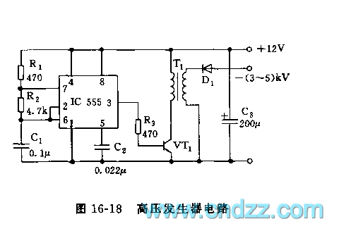
555 high voltage generator circuit
The high voltage generator depicted in figure 16-18 utilizes the 555 timer IC as its primary component. The oscillating voltage produced is enhanced through a step-up transformer. The astable multivibrator configuration comprises the 555 timer along with resistors R1 and...

1 button ON / OFF Switch with 555
This project describes how to build a "soft touch" switch. By "soft touch" we mean that you have to push once to set device ON and push again to set device OFF. This kind of switch works by latching a...

Ultrasonic remote control switch lighting circuit
The T-40-16 and 555 ultrasonic transmitter circuit configuration consists of an ultrasonic transmitter T-40-16 and a 555 timer circuit. By adjusting the potentiometer RP, the oscillation frequency of the circuit can be changed. The output pulse frequency from the 555...

Monostable 555 Multivibrator Working Principle and Circuit diagram with Animation
The monostable 555 timer multivibrator circuit, also known as a one-shot monostable multivibrator, functions as a retriggerable pulse generator. The term "monostable" indicates that the circuit has only one stable state, with the unstable state referred to as the "quasi-stable...
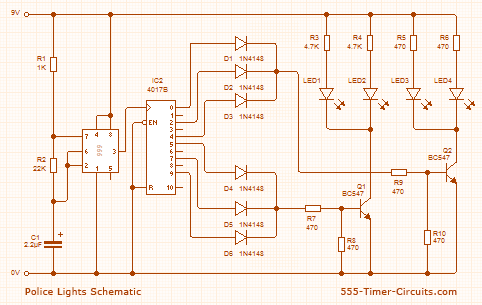
Police Lights associate crystal rectifier Project
This circuit utilizes a 555 timer configured to operate in astable mode. This setup generates a continuous output through Pin 3 in the form of a square wave. When the timer's output transitions to a high state, it triggers the...

Ultrasonic Cleaner Circuit
An ultrasonic cleaner is effective for cleaning specific items. This circuit employs a microcontroller to manage timing and provide a digital display, although a basic oscillator can be utilized if preferred. RESL and RES2 are piezoelectric transducers activated by power...

DC to AC Inverter using 555 Timer
This circuit is a DC to AC inverter utilizing a 555 timer and a transformer with a specification of 9-0-9V/230V and a rating of 36VA. Key components include a 555 integrated circuit (IC), TIP42C, and TIP41C transistors.
The described circuit functions...

temperature control circuit 555 ic
A thermistor is utilized in the circuit for heat sensing, while two 5K variable resistors are incorporated to calibrate the circuit for activating the relay at the desired temperature. The inclusion of a 1N4007 diode across the relay serves to...
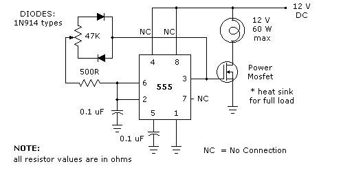
LIGHT DIMMER
The 555 timer light dimmer schematic circuit is shown in figure 1 below. For the light dimmer to work, the 555 timer is configured as a variable cycle astable oscillator running somewhere around 300 Hz. The power MOSFET used here...