


Electronic fuse circuit
#electronic fuse
#overcurrent protection
#short-circuit protection
#workbench
#mains
#isolation
#remote cutout
#adjustable threshold
#indicator lamp

Description: Full short-circuit and overcurrent protection is given by this circuit suitable for workbench applications in technical schools and laboratories where there is a need to work directly with the mains. Additional features are a clearly visible red lamp indicating that the voltage is present, good isolation of the output circuit when the unit is off, only a few millivolts were measured with no load, current threshold adjustable over a limited range and the possibility of remote cutout: the 6V from the secondary can be taken anywhere, normally where you are working, even far away from the protection circuit. More: Pressing the push button will short-circuit the winding and the circuit will switch off thus removing the mains voltage. A suitable led is placed together with the push button to show whether the circuit is in operation or not. Additional remote cutout circuits can be wired in parallel if so required. The circuit will switch off if a short is applied at the output without blowing the fuse but it will blow if you try to activate the circuit if a short is already present. If in doubts, first activate the circuit and then apply the load. The BTB12-600SW is a snubberless triac while the T0805 is a standard triac: you may use other equivalent types but because of the way triacs are driven you cannot use, in this circuit, a snubberless triac instead of a standard triac and vice versa. The 250 µH inductor is a coreless inductor made with 100 turns of 1mm enamelled wire over a form 27mm diameter and 12mm wide. The mains transformer is a standard transformer with split primary wired in such a way that the circuit will self-sustain once it is activated. The same circuit was implemented with a current limit between 0.1 and 0.3A. In this case you have to change the fuse from 6.3A to 1.5A and the sensing resistor from 1Ω to 10Ω.
This circuit design provides robust short-circuit and overcurrent protection, making it ideal for educational and experimental environments where interaction with mains power is necessary. It incorporates a red indicator lamp that illuminates when voltage is present, ensuring users are aware of live conditions. The output circuit is effectively isolated when the unit is turned off, as evidenced by minimal voltage readings (a few millivolts) under no-load conditions.
The circuit features an adjustable current threshold, allowing for fine-tuning of the protection parameters to suit various applications. A remote cutout capability is integrated, enabling the 6V output from the secondary winding to be accessed from a distance, facilitating safe operation even when the protection circuit is not in close proximity.
A push button is included in the design, which, when pressed, shorts the winding, leading to the disconnection of mains voltage. An LED indicator accompanies the push button to visually confirm the operational status of the circuit. The design allows for additional remote cutout circuits to be connected in parallel, enhancing flexibility in system design.
The protection mechanism is designed to trip under short-circuit conditions at the output without blowing the fuse, ensuring minimal disruption. However, if a short is present before the circuit is activated, the fuse will blow, emphasizing the importance of activating the circuit prior to connecting any load.
The circuit employs a BTB12-600SW snubberless triac and a T0805 standard triac, with the stipulation that only equivalent triac types can be used, as the driving characteristics differ significantly between snubberless and standard triacs in this application.
The inductor, rated at 250 µH, is constructed from 100 turns of 1mm enamelled wire wound around a form measuring 27mm in diameter and 12mm in width, contributing to the circuit's performance. The mains transformer utilized is a standard model with a split primary configuration, ensuring that the circuit can sustain itself once activated.
For implementations requiring a lower current limit (between 0.1A and 0.3A), modifications must be made, including replacing the fuse with a 1.5A variant and changing the sensing resistor from 1Ω to 10Ω, thereby adapting the circuit to different operational requirements while maintaining safety and effectiveness.Full short-circuit and overcurrent protection is given by this circuit suitable for workbench applications in technical schools and laboratories where there is a need to work directly with the mains. Additional features are a clearly visible red lamp indicating that the voltage is present, good isolation of the output circuit when the unit is off, only a few millivolts were measured with no load, current threshold adjustable over a limited range and the possibility of remote cutout: the 6V from the secondary can be taken anywhere, normally where you are working, even far away from the protection circuit.
Pressing the push button will short-circuit the winding and the circuit will switch off thus removing the mains voltage. A suitable led is placed together with the push button to show whether the circuit is in operation or not.
Additional remote cutout circuits can be wired in parallel if so required. The circuit will switch off if a short is applied at the output without blowing the fuse but it will blow if you try to activate the circuit if a short is already present. If in doubts, first activate the circuit and then apply the load. The BTB12-600SW is a snubberless triac while the T0805 is a standard triac: you may use other equivalent types but because of the way triacs are driven you cannot use, in this circuit, a snubberless triac instead of a standard triac and viceversa.
The 250 ?H inductor is a coreless inductor made with 100 turns of 1mm enamelled wire over a form 27mm diameter and 12mm wide. The mains transformer is a standard transformer with split primary wired in such a way that the circuit will self-sustain once it is activated.
The same circuit was implemented with a current limit between 0.1 and 0.3A. In this case you have to change the fuse from 6.3A to 1.5A and the sensing resistor from 1? to 10?.
This circuit design provides robust short-circuit and overcurrent protection, making it ideal for educational and experimental environments where interaction with mains power is necessary. It incorporates a red indicator lamp that illuminates when voltage is present, ensuring users are aware of live conditions. The output circuit is effectively isolated when the unit is turned off, as evidenced by minimal voltage readings (a few millivolts) under no-load conditions.
The circuit features an adjustable current threshold, allowing for fine-tuning of the protection parameters to suit various applications. A remote cutout capability is integrated, enabling the 6V output from the secondary winding to be accessed from a distance, facilitating safe operation even when the protection circuit is not in close proximity.
A push button is included in the design, which, when pressed, shorts the winding, leading to the disconnection of mains voltage. An LED indicator accompanies the push button to visually confirm the operational status of the circuit. The design allows for additional remote cutout circuits to be connected in parallel, enhancing flexibility in system design.
The protection mechanism is designed to trip under short-circuit conditions at the output without blowing the fuse, ensuring minimal disruption. However, if a short is present before the circuit is activated, the fuse will blow, emphasizing the importance of activating the circuit prior to connecting any load.
The circuit employs a BTB12-600SW snubberless triac and a T0805 standard triac, with the stipulation that only equivalent triac types can be used, as the driving characteristics differ significantly between snubberless and standard triacs in this application.
The inductor, rated at 250 µH, is constructed from 100 turns of 1mm enamelled wire wound around a form measuring 27mm in diameter and 12mm in width, contributing to the circuit's performance. The mains transformer utilized is a standard model with a split primary configuration, ensuring that the circuit can sustain itself once activated.
For implementations requiring a lower current limit (between 0.1A and 0.3A), modifications must be made, including replacing the fuse with a 1.5A variant and changing the sensing resistor from 1Ω to 10Ω, thereby adapting the circuit to different operational requirements while maintaining safety and effectiveness.Full short-circuit and overcurrent protection is given by this circuit suitable for workbench applications in technical schools and laboratories where there is a need to work directly with the mains. Additional features are a clearly visible red lamp indicating that the voltage is present, good isolation of the output circuit when the unit is off, only a few millivolts were measured with no load, current threshold adjustable over a limited range and the possibility of remote cutout: the 6V from the secondary can be taken anywhere, normally where you are working, even far away from the protection circuit.
Pressing the push button will short-circuit the winding and the circuit will switch off thus removing the mains voltage. A suitable led is placed together with the push button to show whether the circuit is in operation or not.
Additional remote cutout circuits can be wired in parallel if so required. The circuit will switch off if a short is applied at the output without blowing the fuse but it will blow if you try to activate the circuit if a short is already present. If in doubts, first activate the circuit and then apply the load. The BTB12-600SW is a snubberless triac while the T0805 is a standard triac: you may use other equivalent types but because of the way triacs are driven you cannot use, in this circuit, a snubberless triac instead of a standard triac and viceversa.
The 250 ?H inductor is a coreless inductor made with 100 turns of 1mm enamelled wire over a form 27mm diameter and 12mm wide. The mains transformer is a standard transformer with split primary wired in such a way that the circuit will self-sustain once it is activated.
The same circuit was implemented with a current limit between 0.1 and 0.3A. In this case you have to change the fuse from 6.3A to 1.5A and the sensing resistor from 1? to 10?.
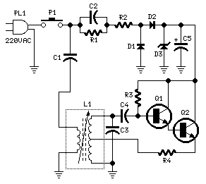
Mains Remote Alarm
Beeper and/or LED remotely-operated via mains supply line. Pressing the pushbutton of the transmitter, a sound and/or light alert is activated in the receiver. The system uses no wiring or radio frequencies: the transmitted signal is conveyed into the mains...

Mains Light dimmer
A simple mains Light dimmer.
A simple mains light dimmer is an electronic device used to adjust the brightness of incandescent and some LED lights by varying the voltage and current supplied to the light bulb. The typical operation of a...

Mains Failure Indicator
When the mains voltage is present at the input terminals, the transistor in the optocoupler is activated, T1 is off, and the silicon-controlled rectifier (SCR) Th1 is in the conducting state. As a result, both terminals of the piezoelectric buzzer...

Electronic Fuse / Low Pass Filter
This is adjustable electronic fuse that can be used to protect power supplies from short circuits or can be also used to limit the current usage. It can be adjusted for currents from 100mA up to 4.3A.
An adjustable electronic fuse...

Electronic Fuse Employs A Relay
While many power supplies can be set to limit their output current to a defined level to protect the circuit they are powering, no such protection is available.
To enhance the safety and reliability of electronic circuits, it is crucial to...
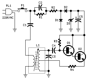
Mains Remote Tranciever Alarm
Pressing the pushbutton of the transmitter, a sound and/or light alert is activated in the receiver. The system uses no wiring or radio frequencies: the transmitted signal is conveyed into the mains supply line. It can be used at home,...

Mains Remote-Alert circuit
Pressing the pushbutton on the transmitter activates a sound and/or light alert in the receiver. This system operates without wiring or radio frequencies; instead, the transmitted signal is conveyed through the mains supply line. It is suitable for use in...
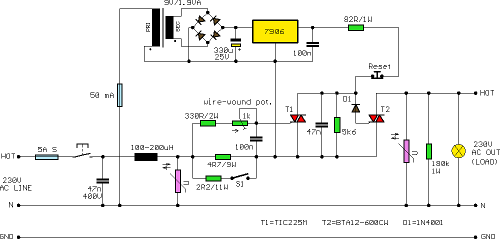
Fast Electronic Fuse
A fast electronic fuse designed to operate on 230V AC with an adjustable trip current. When the current through the load exceeds a level determined by the user, the fuse will trip to protect the circuit.
The electronic fuse functions as...

Indicator-lamp-driver
A simple solid-state relay circuit drives the 10-Vac telephone indicator lamps from logic circuitry while maintaining complete isolation between the 10-V line and the logic circuit.
The described circuit utilizes a solid-state relay (SSR) to control 10-Vac telephone indicator lamps using...