


Multiplexed output digital camera power supply circuit composed of MAX1802
#MAX1802
#buck converter
#boost converter
#voltage regulation
#digital camera
#adjustable output
#power management
#efficiency
#DC-DC converter
#multiple output

Description: The circuit diagram for a multiple output digital camera power supply using the MAX1802 is illustrated below. The MAX1802 chip features two buck converters and three boost converters. It accepts an input voltage range of 2.5 to 11V and provides a continuously adjustable output voltage from 2.7 to 5.5V. The minimum output voltage can be set to 1.25V. The operating frequency of the MAX1802 can be adjusted to 1MHz, ensuring efficient voltage conversion.
The MAX1802 is designed for applications requiring multiple output voltages, such as digital cameras, where various components operate at different voltage levels. The two buck converters step down higher input voltages to lower output voltages, while the three boost converters increase lower voltages to the necessary levels for powering specific components.
The input voltage range of 2.5 to 11V allows for flexibility in power supply options, accommodating a variety of battery configurations and other power sources. The adjustable output voltage from 2.7 to 5.5V enables compatibility with a wide range of digital camera components, such as image sensors, processors, and display modules. Additionally, the ability to set the output voltage as low as 1.25V is particularly useful for powering low-voltage components, thereby enhancing overall system efficiency.
The adjustable operating frequency of 1MHz is beneficial for optimizing the performance of the converters. A higher frequency can reduce the size of external components such as inductors and capacitors, which is advantageous in compact designs. The efficiency of the conversion process is crucial for battery-operated devices, as it directly impacts battery life and thermal performance. The MAX1802 is engineered to maintain high conversion efficiency across various load conditions, which is essential for the reliability and longevity of digital camera systems.
In summary, the MAX1802 provides a versatile and efficient solution for powering digital camera systems with multiple voltage requirements, ensuring optimal performance and adaptability in a compact design.Composed of MAX1802 multiple output digital camera power supply circuit diagram is shown as below. MAX1802 Chip has 2 buck converters and 3 boost converters. Input voltage 2.5?11V, continuously adjustable output voltage 2.7?5.5V. The lowest output voltage can be ajdusted to 1.25V. The working rate of MAX1802 can be adjusted to 1MHz and conversion efficienc..
The MAX1802 is designed for applications requiring multiple output voltages, such as digital cameras, where various components operate at different voltage levels. The two buck converters step down higher input voltages to lower output voltages, while the three boost converters increase lower voltages to the necessary levels for powering specific components.
The input voltage range of 2.5 to 11V allows for flexibility in power supply options, accommodating a variety of battery configurations and other power sources. The adjustable output voltage from 2.7 to 5.5V enables compatibility with a wide range of digital camera components, such as image sensors, processors, and display modules. Additionally, the ability to set the output voltage as low as 1.25V is particularly useful for powering low-voltage components, thereby enhancing overall system efficiency.
The adjustable operating frequency of 1MHz is beneficial for optimizing the performance of the converters. A higher frequency can reduce the size of external components such as inductors and capacitors, which is advantageous in compact designs. The efficiency of the conversion process is crucial for battery-operated devices, as it directly impacts battery life and thermal performance. The MAX1802 is engineered to maintain high conversion efficiency across various load conditions, which is essential for the reliability and longevity of digital camera systems.
In summary, the MAX1802 provides a versatile and efficient solution for powering digital camera systems with multiple voltage requirements, ensuring optimal performance and adaptability in a compact design.Composed of MAX1802 multiple output digital camera power supply circuit diagram is shown as below. MAX1802 Chip has 2 buck converters and 3 boost converters. Input voltage 2.5?11V, continuously adjustable output voltage 2.7?5.5V. The lowest output voltage can be ajdusted to 1.25V. The working rate of MAX1802 can be adjusted to 1MHz and conversion efficienc..

psu
The Chameleon II Power Supply Circuits convert the raw input supply into stable voltage outputs necessary for the Chameleon interfaces. The outputs provided are +5V, +12V, and -12V.
The Chameleon II Power Supply Circuits are designed to ensure reliable operation of...
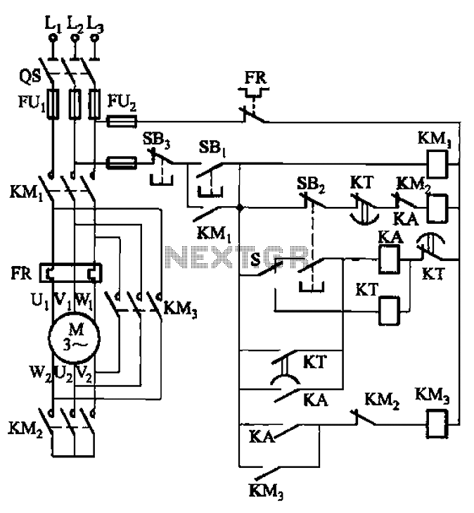
Y- buck can be manual and automatic control of the starting circuit
The circuit is depicted. It is capable of both manual and automatic control.
The circuit in question is designed to facilitate dual modes of operation: manual and automatic control. This versatility allows users to engage with the system according to their...

free diy open source boost driver
How would you like free boost driver designs? Although it is not possible to control anyone's actions, any individual interested in selling this circuit would be appreciated.
The boost driver circuit is a type of DC-DC converter designed to step up...

periodic steady state analysis for dc to dc converters
Connect with Cadence technologists and peers in the Cadence Community. Stay informed about technology trends, news, and opinions through blogs, forums, and social networking.
The Cadence Community serves as a collaborative platform for professionals in the electronics design automation (EDA) field....

Boost Converter Design
Ignore components C1, C2, R3. The MOSFET, Q1, switches on, creating a short circuit between the right-hand side of the inductor, L1, and ground (0V). A fixed voltage of 3.3V is applied across the inductor, causing its current to ramp...

ciruits and chematics
This is the current schematic for the Boost converter. The negative power is connected to the emitters and the LED cathode. With the values shown, the circuit draws approximately 18 mA and drives the LED to around 5 mA. A...

Variable Voltage Regulation
Controlling the output voltage from a regulator can be made variable in three ways:
1. Using a fixed reference zener diode to increase the output by the value of the zener
2. A variable resistor for variable output, note that...

0-30 VDC Stabilized Power Supply with Current Control 0.002-3 A
The circuit begins with a step-down mains transformer featuring a secondary winding rated at 24 V/3 A, which connects across the input points at pins 1 and 2. The quality of the output supply is directly related to the transformer's...

3A Dc-Dc Converter Needs No Heatsink Circuit
This regulator achieves 90% efficiency with a 12-V input and a 5-V output. It utilizes the LT1158 and LT1431 components from Linear Technology, Inc. High efficiency is accomplished by synchronously switching two power MOSFETs in a step-down switching regulator. The...