


Power supply monitor
#voltage monitor
#LED indicator
#power supply
#voltage threshold
#tricolor LED
#voltage range
#circuit protection
#voltage detection
#power management

Description: This circuit utilizes a tricolor LED display to signify acceptable and unacceptable output voltages. One LED indicates the upper voltage limit, while another indicates the lower voltage limit. When the monitored voltage exceeds the maximum set point, the LED display illuminates red. A yellow LED activates for voltages that fall below the minimum set point, and a green LED lights up for voltages that are within the acceptable range between the high and low settings. The circuit is powered by the voltage it monitors, eliminating the need for an additional power supply. Furthermore, the circuit can be adapted to monitor voltage differences between two power supplies. If the monitored voltages differ by more than a predetermined threshold, a visual or audible alarm alerts the operator. The circuit can also be modified for remote monitoring and the option to use a separate power supply.
The described circuit employs a tricolor LED display, which serves as a visual indicator for voltage levels in a monitored system. The circuit includes voltage reference points, typically set using potentiometers, to define the upper and lower voltage thresholds. These reference points are compared against the monitored voltage via a microcontroller or comparator circuit.
The green LED indicates normal operating conditions, lighting up when the monitored voltage is within the defined range. The red LED activates when the voltage exceeds the upper limit, signaling a critical condition that requires immediate attention. Conversely, the yellow LED serves as an alert for voltages that fall below the lower limit, indicating potential system failure or malfunction.
The circuit's design allows for flexibility in application; it can be configured to monitor voltage levels for a single power supply or to compare two different voltages. In the latter case, additional components such as differential amplifiers may be utilized to accurately measure the voltage difference. The alarm system can be implemented using simple buzzer circuits or more sophisticated sound modules, depending on the required alerting mechanism.
For remote monitoring capabilities, the circuit can incorporate wireless transmission modules, such as Wi-Fi or Bluetooth, enabling real-time feedback to an operator's device. This feature enhances system oversight, especially in industrial environments where immediate responses to voltage fluctuations are crucial.
Overall, the circuit's ability to operate without an external power supply, combined with its adaptability for various monitoring scenarios, makes it a versatile tool in electronic applications.This circuit uses a tricolor LED display to indicate acceptable and unacceptable output voltages. One to set the upper voltage limit, the other, the lower voltage limit. When the monitored voltage is above the set maximum, the LED display turns red. Yellow turns On for voltages below the set minimum, and green turns on for voltages between the high and the low settings. The circuit does not need a separate power supply. It is powered by the voltage it monitors. The circuit can be adapted to monitor voltage differences between two power supplies. Should the monitored voltages differ by more than a set value, a visual or an audible alarm would warn the operator about the difference. The circuit can also be modified for remote monitoring and the use of a separate power supply.
The described circuit employs a tricolor LED display, which serves as a visual indicator for voltage levels in a monitored system. The circuit includes voltage reference points, typically set using potentiometers, to define the upper and lower voltage thresholds. These reference points are compared against the monitored voltage via a microcontroller or comparator circuit.
The green LED indicates normal operating conditions, lighting up when the monitored voltage is within the defined range. The red LED activates when the voltage exceeds the upper limit, signaling a critical condition that requires immediate attention. Conversely, the yellow LED serves as an alert for voltages that fall below the lower limit, indicating potential system failure or malfunction.
The circuit's design allows for flexibility in application; it can be configured to monitor voltage levels for a single power supply or to compare two different voltages. In the latter case, additional components such as differential amplifiers may be utilized to accurately measure the voltage difference. The alarm system can be implemented using simple buzzer circuits or more sophisticated sound modules, depending on the required alerting mechanism.
For remote monitoring capabilities, the circuit can incorporate wireless transmission modules, such as Wi-Fi or Bluetooth, enabling real-time feedback to an operator's device. This feature enhances system oversight, especially in industrial environments where immediate responses to voltage fluctuations are crucial.
Overall, the circuit's ability to operate without an external power supply, combined with its adaptability for various monitoring scenarios, makes it a versatile tool in electronic applications.This circuit uses a tricolor LED display to indicate acceptable and unacceptable output voltages. One to set the upper voltage limit, the other, the lower voltage limit. When the monitored voltage is above the set maximum, the LED display turns red. Yellow turns On for voltages below the set minimum, and green turns on for voltages between the high and the low settings. The circuit does not need a separate power supply. It is powered by the voltage it monitors. The circuit can be adapted to monitor voltage differences between two power supplies. Should the monitored voltages differ by more than a set value, a visual or an audible alarm would warn the operator about the difference. The circuit can also be modified for remote monitoring and the use of a separate power supply.
Power Management
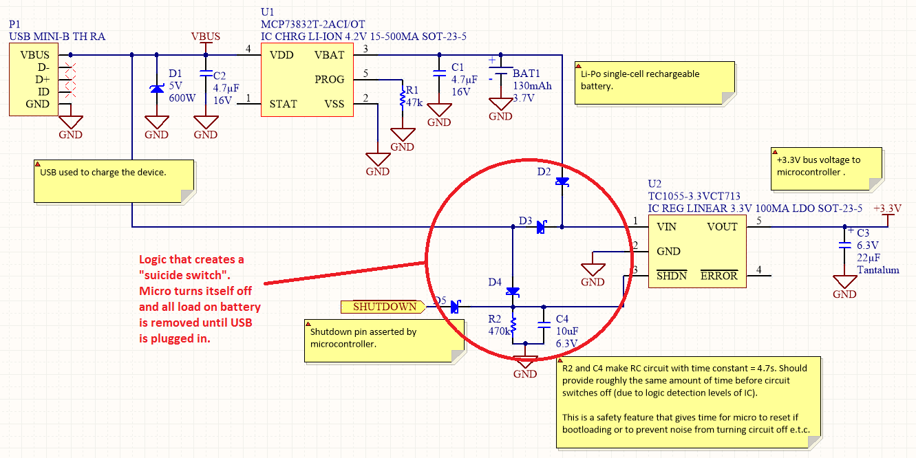
Overview Disabling Sections of a Circuit The "Suicide Switch" Overview Power management is a significant design consideration for battery-powered devices.
Power management is a crucial aspect of circuit design, particularly in battery-powered applications where energy efficiency directly impacts the operational lifespan...

electronic circuit breaker
A circuit breaker is an automatically operated electrical switch designed to protect an electrical circuit from damage caused by overload or short circuit. Its basic function is to detect a fault condition and, by interrupting continuity, immediately discontinue electrical flow....

FSP107-2PS01 two-in-one power panel circuit analysis
The main component is the LG26 one-inch screens integrated with the FSP107-2PS01 two-in-one electrical power package, which utilizes a direct drive CCFL modulator tube. This setup is compatible with screens from other manufacturers, such as Samsung and AU, but requires...

Output sampling winding isolated switching power supply
The diagram illustrates the output sampling winding of an isolated switching power supply. In the diagram, T represents a high-frequency transformer; N2 denotes the self-oscillation positive feedback winding; N3 is the error amplifier; VTS is the winding that provides the...

Sanyo 83P switching power supply circuit diagram
Oscillation: The positive terminal voltage of C310 is approximately 300V. The resistors R311 and R312 are connected to the switch BG311 at the B pole, while the B301 winding via the switching transformer (4) and (6) is connected to the...

Micropower double ended limit detector
The detector utilizes three sections of an L144 and a DC4011 type CMOS NAND gate to create a very low power voltage monitor. If the input voltage, Vin, is above Vhigh or below Vlow, the output will be a logical...

Saving voltage regulator circuit
This document presents a power-saving voltage regulator circuit. In addition to its general function as a delay regulator, the circuit features: (1) an automatic voltage regulation capability for mains voltage within a range of 220V ±10%, allowing direct power supply...

Industrial fuel oil furnace controller circuit diagram 2
The industrial fuel oil furnace controller circuit consists of a power supply circuit, a testing and ignition control circuit, and a control implementation circuit, as illustrated in the accompanying diagram. The power supply circuit includes a step-down capacitor (C6), a...

Power Supply Wiring Diagram For Nissan 300ZX
This circuit illustrates the power supply wiring diagram for the Nissan 300ZX, a sports car known as the Fairlady Z. Components include the lighting switch, ECCS, and fuse.
The power supply wiring diagram for the Nissan 300ZX is essential for understanding...