


UPS Power Supply
#UPS
#regulated
#unregulated
#battery backup
#voltage regulator
#power management
#backup power
#7815 regulator
#12V supply

Description: This circuit is a simple form of the commercial UPS, the circuit provides a constant regulated 5 Volt output and an unregulated 12 Volt supply. In the event of electrical supply line failure the battery takes over, with no spikes on the regulated supply. This circuit can be adapted for other regulated and unregulated voltages by using different regulators and batteries. For a 15 Volt regulated supply use two 12 Volt batteries in series and a 7815 regulator. There is a lot of flexibility in this circuit. More: TR1 has a primary matched to the local electrical supply which is 240 Volts in the UK. The secondary winding should be rated at least 12 Volts at 2 amp, but can be higher, for example 15 Volts. FS1 is a slow blow type and protects against short circuits.
The circuit operates as a basic Uninterruptible Power Supply (UPS) designed to provide both regulated and unregulated voltage outputs. The main components include a transformer (TR1), a rectifier, a voltage regulator, and a battery backup system.
TR1 is a step-down transformer with a primary winding designed for the local electrical supply voltage, specifically rated for 240 Volts in the UK. Its secondary winding is configured to output a minimum of 12 Volts at 2 Amps, although it can be designed for higher voltages, such as 15 Volts, depending on the application requirements. The transformer’s output is connected to a rectifier circuit, which converts the AC voltage to a DC voltage suitable for battery charging and powering the load.
The circuit features a battery backup system that engages automatically during power outages. The battery, which can be selected based on the desired output voltage, ensures continuous power supply without interruption. The regulated output is achieved using a linear voltage regulator, such as the 7805 for 5 Volts or the 7815 for 15 Volts, which maintains a stable output voltage even in the event of fluctuations in the input voltage.
In terms of safety, a slow-blow fuse (FS1) is included to protect against short circuits and overcurrent situations. This fuse allows for temporary surges in current, which may occur during normal operation, but will blow if a sustained overcurrent condition arises, thereby protecting the circuit components.
The flexibility of this UPS circuit allows for customization according to the specific voltage requirements of different applications. By selecting appropriate regulators and battery configurations, users can easily adapt the circuit to meet various power supply needs. The design also emphasizes reliability, ensuring that the regulated supply remains free from voltage spikes during switchover from mains power to battery power.This circuit is a simple form of the commercial UPS, the circuit provides a constant regulated 5 Volt output and an unregulated 12 Volt supply. In the event of electrical supply line failure the battery takes over, with no spikes on the regulated supply.
This circuit can be adapted for other regulated and unregulated voltages by using different regulators and batteries. For a 15 Volt regulated supply use two 12 Volt batteries in series and a 7815 regulator. There is a lot of flexibility in this circuit. TR1 has a primary matched to the local electrical supply which is 240 Volts in the UK. The secondary winding should be rated at least 12 Volts at 2 amp, but can be higher, for example 15 Volts. FS1 is a slow blow type and protects against short circuits o
The circuit operates as a basic Uninterruptible Power Supply (UPS) designed to provide both regulated and unregulated voltage outputs. The main components include a transformer (TR1), a rectifier, a voltage regulator, and a battery backup system.
TR1 is a step-down transformer with a primary winding designed for the local electrical supply voltage, specifically rated for 240 Volts in the UK. Its secondary winding is configured to output a minimum of 12 Volts at 2 Amps, although it can be designed for higher voltages, such as 15 Volts, depending on the application requirements. The transformer’s output is connected to a rectifier circuit, which converts the AC voltage to a DC voltage suitable for battery charging and powering the load.
The circuit features a battery backup system that engages automatically during power outages. The battery, which can be selected based on the desired output voltage, ensures continuous power supply without interruption. The regulated output is achieved using a linear voltage regulator, such as the 7805 for 5 Volts or the 7815 for 15 Volts, which maintains a stable output voltage even in the event of fluctuations in the input voltage.
In terms of safety, a slow-blow fuse (FS1) is included to protect against short circuits and overcurrent situations. This fuse allows for temporary surges in current, which may occur during normal operation, but will blow if a sustained overcurrent condition arises, thereby protecting the circuit components.
The flexibility of this UPS circuit allows for customization according to the specific voltage requirements of different applications. By selecting appropriate regulators and battery configurations, users can easily adapt the circuit to meet various power supply needs. The design also emphasizes reliability, ensuring that the regulated supply remains free from voltage spikes during switchover from mains power to battery power.This circuit is a simple form of the commercial UPS, the circuit provides a constant regulated 5 Volt output and an unregulated 12 Volt supply. In the event of electrical supply line failure the battery takes over, with no spikes on the regulated supply.
This circuit can be adapted for other regulated and unregulated voltages by using different regulators and batteries. For a 15 Volt regulated supply use two 12 Volt batteries in series and a 7815 regulator. There is a lot of flexibility in this circuit. TR1 has a primary matched to the local electrical supply which is 240 Volts in the UK. The secondary winding should be rated at least 12 Volts at 2 amp, but can be higher, for example 15 Volts. FS1 is a slow blow type and protects against short circuits o
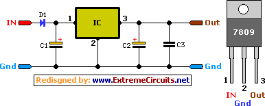
9 Volt 2 Ampere DC Power SupplyCircuit
A simple 9 Volt, 2 amp power supply utilizing a single integrated circuit (IC) regulator. This circuit is straightforward, as the regulator handles the majority of the work. The component used is the 7809 voltage regulator.
The circuit consists primarily of...

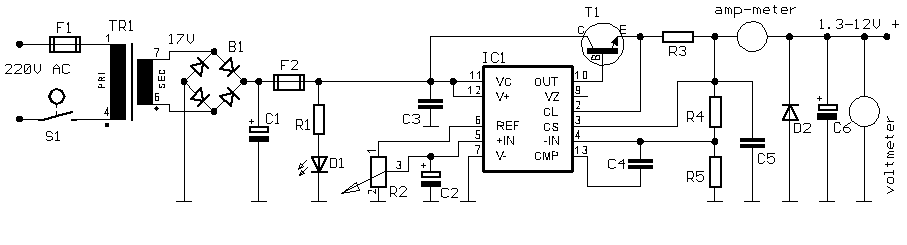
Variable Power Supply
Using the versatile L200 voltage regulator, this power supply has independent voltage and current limits. The mains transformer has a 12-volt, 2 amp rated secondary, the primary winding should equal the electricity supply in your country, which is 240V here...
Small Variable power Supply
This is a simple yet reliable device based on one of the oldest integrated voltage regulators, the LM723.
The LM723 is a versatile voltage regulator that can be configured to provide a wide range of output voltages. It is capable of...
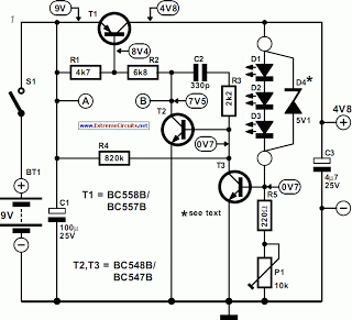
thrifty voltage regulator
One of the drawbacks of a three-pin voltage regulator is that the input voltage needs to be 2.5 to 3 V higher than the output voltage. This makes these integrated regulators unsuitable for battery power supplies. For instance, if the...

Self switching Power Supply
Self-switching power supply. One of the main features of the regulated power supply circuit being presented is that, although a fixed-voltage regulator LM7805 is used in the circuit, its.
The self-switching power supply circuit utilizes the LM7805 voltage regulator to maintain...

Logic PSU with Overvoltage Protection
The 5 volt regulated power supply for TTL and 74LS series integrated circuits has to be very precise and tolerant of voltage transients. These ICs are easily damaged by short voltage spikes. A fuse will blow when its current rating...

Battery Backup for SRAM or Microcontroller
This circuit functions as a low-cost battery backup solution for SRAM and microcontroller/microprocessor applications. It utilizes 1N4148 diodes to prevent battery discharge back to the power source. Diode D8 provides a one-way path for charging the battery through resistor R13,...

UPS Schematic
UPS Schematic Circuit Diagram for a 3000 Watts UPS. It can also function for 1000 VA with minor modifications.
The schematic circuit diagram for a 3000 Watts Uninterruptible Power Supply (UPS) is designed to provide reliable backup power in the event...

MAKING YOUR OWN REGULATED POWER SUPPLY
This document presents a basic electronics project focused on creating a regulated power supply. A regulated power supply is essential for various electronic circuits, as it provides a constant voltage necessary for their operation. Understanding how to construct a regulated...