


5 watt, 80 meter QRP CW Transceiver
#QRP
#CW Transceiver
#power MOSFET
#superhetrodyne receiver
#varactor diode
#T/R switching
#RF amplifier
#80 meter band
#ham radio
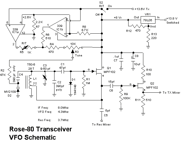
Description: 1. Full 5 watt output using a power MOSFET final that is resistant to high SWR and thermal runaway. This final is very efficient and runs much cooler than traditional bipolar designs. 2. Highly sensitive and selective superhetrodyne receiver with plenty of audio to drive a speaker. About 100 Khz of tuning range is provided through a varactor diode along with a switchable RIT control. 3. Full break-in keying with a unique T/R switching system. Work is continuing on a printed circuit board and this circuit is expected to be available as a complete kit including all electronic parts, PCB and instruction manual at a future date. My prototype was built on Radio Shack universal boards. More: This month, we`ll begin by building the VFO. The VFO uses a JFET for stability and a varactor diode to provide the necessary tuning. Many other JFET`s such as the 2N3819 or 2N4416 can be substituted for Q1 and Q2 but pay attention to the pinouts.
The described circuit integrates several advanced features aimed at providing a robust and efficient radio communication system. The power output stage utilizes a power MOSFET, which is known for its ability to handle high Voltage Standing Wave Ratio (SWR) conditions without succumbing to thermal runaway, a common issue in traditional bipolar transistor designs. This results in an output of 5 watts, ensuring sufficient power for effective transmission while maintaining a cooler operating temperature.
The receiver section employs a superhetrodyne architecture, which is characterized by its high sensitivity and selectivity. This design allows the receiver to effectively filter and amplify desired signals while minimizing noise. The tuning range of approximately 100 kHz is achieved through the use of a varactor diode, which enables smooth frequency adjustments. Additionally, a switchable Receiver Incremental Tuning (RIT) control enhances operational flexibility, allowing users to fine-tune their reception as needed.
The circuit also features a full break-in keying capability, facilitated by an innovative Transmit/Receive (T/R) switching system. This feature is crucial for operators who require immediate switching between transmitting and receiving modes without delay, thus improving communication efficiency.
Development is ongoing for a printed circuit board (PCB) layout, which will streamline assembly and enhance the reliability of the circuit. The final product is anticipated to be offered as a complete kit, inclusive of all necessary electronic components, the PCB, and a comprehensive instruction manual, making it accessible for hobbyists and engineers alike.
The Variable Frequency Oscillator (VFO) is a critical component of this design, employing a Junction Field Effect Transistor (JFET) to achieve stability. The inclusion of a varactor diode for tuning further enhances the VFO's performance. Compatible alternatives for the JFETs, such as the 2N3819 or 2N4416, can be utilized for Q1 and Q2, provided that the pin configurations are correctly matched to ensure proper functionality. This attention to detail in component selection and circuit design underscores the overall quality and reliability of the system.1. Full 5 watt output using a power MOSFET final that is resistant to high SWR and thermal runaway. This final is very efficient and runs much cooler than traditional bipolar designs. 2. Highly sensitive and selective superhetrodyne receiver with plenty of audio to drive a speaker. About 100 Khz of tuning range is provided through a varactor diode along with a switchable RIT control. 3. Full break-in keying with a unique T/R switching system. Work is continuing on a printed circuit board and this circuit is expected to be available as a complete kit including all electronic parts, PCB and instruction manual at a future date.
My prototype was built on Radio Shack universal boards. This month, we`ll begin by building the VFO. The VFO uses a JFET for stability and a varactor diode to provide the necessary tuning. Many other JFET`s such as the 2N3819 or 2N4416 can be substituted for Q1 and Q2 but pay attention to the pinouts
The described circuit integrates several advanced features aimed at providing a robust and efficient radio communication system. The power output stage utilizes a power MOSFET, which is known for its ability to handle high Voltage Standing Wave Ratio (SWR) conditions without succumbing to thermal runaway, a common issue in traditional bipolar transistor designs. This results in an output of 5 watts, ensuring sufficient power for effective transmission while maintaining a cooler operating temperature.
The receiver section employs a superhetrodyne architecture, which is characterized by its high sensitivity and selectivity. This design allows the receiver to effectively filter and amplify desired signals while minimizing noise. The tuning range of approximately 100 kHz is achieved through the use of a varactor diode, which enables smooth frequency adjustments. Additionally, a switchable Receiver Incremental Tuning (RIT) control enhances operational flexibility, allowing users to fine-tune their reception as needed.
The circuit also features a full break-in keying capability, facilitated by an innovative Transmit/Receive (T/R) switching system. This feature is crucial for operators who require immediate switching between transmitting and receiving modes without delay, thus improving communication efficiency.
Development is ongoing for a printed circuit board (PCB) layout, which will streamline assembly and enhance the reliability of the circuit. The final product is anticipated to be offered as a complete kit, inclusive of all necessary electronic components, the PCB, and a comprehensive instruction manual, making it accessible for hobbyists and engineers alike.
The Variable Frequency Oscillator (VFO) is a critical component of this design, employing a Junction Field Effect Transistor (JFET) to achieve stability. The inclusion of a varactor diode for tuning further enhances the VFO's performance. Compatible alternatives for the JFETs, such as the 2N3819 or 2N4416, can be utilized for Q1 and Q2, provided that the pin configurations are correctly matched to ensure proper functionality. This attention to detail in component selection and circuit design underscores the overall quality and reliability of the system.1. Full 5 watt output using a power MOSFET final that is resistant to high SWR and thermal runaway. This final is very efficient and runs much cooler than traditional bipolar designs. 2. Highly sensitive and selective superhetrodyne receiver with plenty of audio to drive a speaker. About 100 Khz of tuning range is provided through a varactor diode along with a switchable RIT control. 3. Full break-in keying with a unique T/R switching system. Work is continuing on a printed circuit board and this circuit is expected to be available as a complete kit including all electronic parts, PCB and instruction manual at a future date.
My prototype was built on Radio Shack universal boards. This month, we`ll begin by building the VFO. The VFO uses a JFET for stability and a varactor diode to provide the necessary tuning. Many other JFET`s such as the 2N3819 or 2N4416 can be substituted for Q1 and Q2 but pay attention to the pinouts

100W Transmitter RF Power Amplifier 2SC2782
This is a 6-meter band transmitter RF power amplifier designed for 50 MHz operation, delivering an output power of 100 watts. It is intended for use with the FT-736R transceiver and is driven by a 10-watt signal for 6-meter SSB...

300W FM RF Amplifier Circuit
This 300W RF power amplifier for an FM transmitter utilizes 2 x TP9383 transistors. It operates within the 88 - 108 MHz frequency band.
The 300W RF power amplifier is designed specifically for FM transmission applications, providing high power output suitable...
rf amplifier with op amp
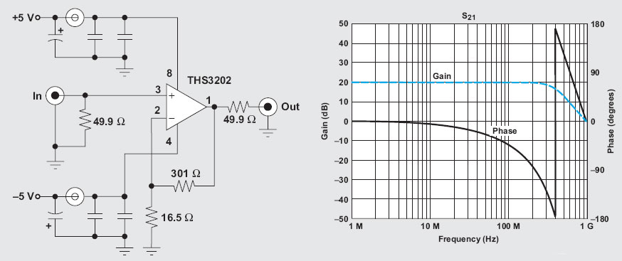
The operational amplifier (op-amp) has a significant history, particularly with the 741/301 series, which has been popular for approximately 20 years due to its ease of calculation (gain calculation), affordability, and simplicity of construction. The versatility of op-amps allows for...

AM-FM-TV RF AMPLIFIER
The circuit is a universal amplifier capable of amplifying any RF signal. The BF194 or BF198 transistors can be utilized. Coaxial cable should be used for connections. Additional components include: R1=22K, R2=100K, R3=18, R4=1.2K, C1=470PF, C2=470PF, C3=1NF, and T=BF194 or...

RF amplifier and filter for 70 MHz
The RF amplifier utilizes noiseless feedback via the drain-gate capacitance, incorporating an inductor in the source lead to achieve the required 90-degree phase shift between the gate voltage and channel current.
The RF amplifier is designed to enhance signal strength while...

Mic wiring Servicing and alignment
The FDK Multi-750e was introduced in the UK in 1981. This 2-meter ham radio multimode transceiver is offered at an attractive price and includes a matching 70cm transverter that can be controlled directly from the front panel. While many units...

10 GHZ Transverter
A number of amateur radio operators have begun their journey in the 10 GHz band using surplus microwave transceivers manufactured by M/A-Com, commonly referred to as "White Boxes." These devices can be modified to function as transverters, which convert signals...
The CIRCLOMOS
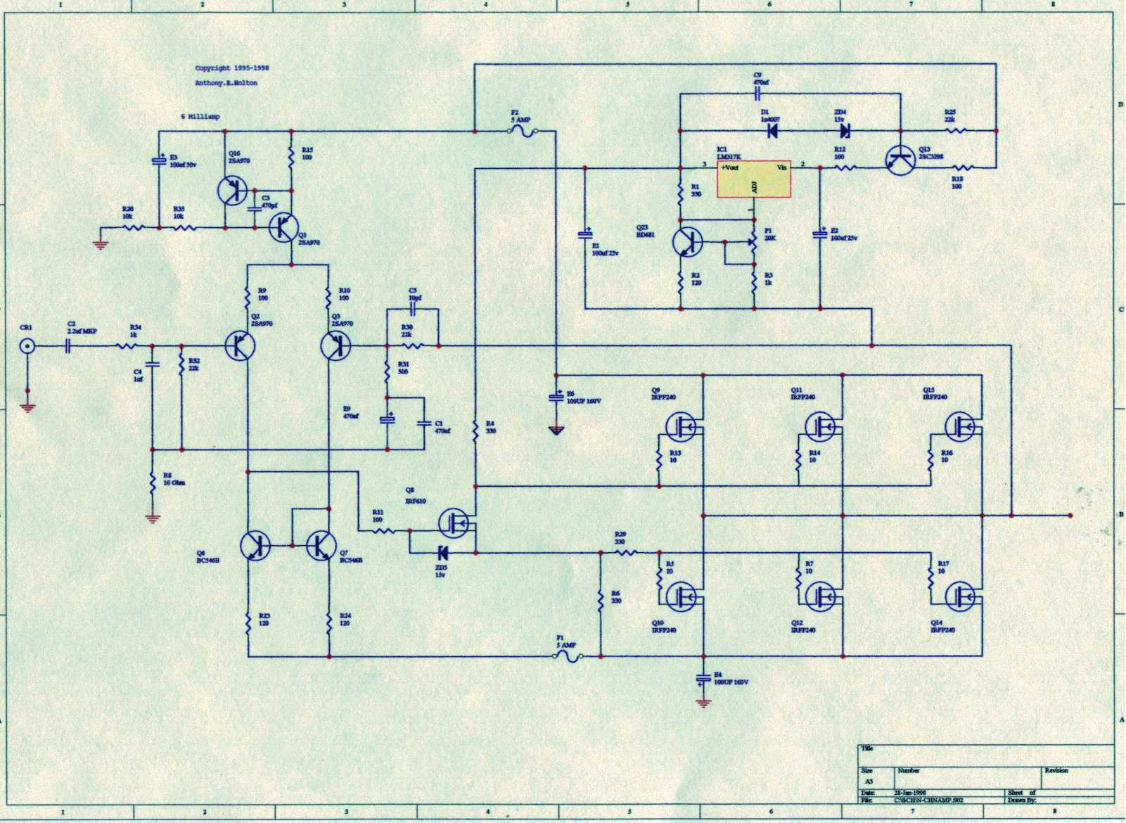
Unfortunately, only RF amplifier devices are available, with the lowest frequency being 10 KHz.
The circuit in question pertains to RF (radio frequency) amplification, specifically focusing on devices that operate with a minimum frequency threshold of 10 KHz. RF amplifiers...

50mhz 300w mosfet amplifier circuit
An RF power amplifier is an electronic amplifier used to convert a low-power radio-frequency signal into a larger signal of significant power, typically for driving the antenna of a transmitter. It is optimized for high efficiency, high output power (P1dB)...