


50Mhz Rf Bridge Circuit
#RF bridge
#50MHz
#antenna measurement
#amateur radio
#potentiometer
#linear
#measurement circuit
#RF components
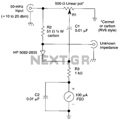
Description: The bridge shown was used for measurements on 50-MHz amateur radio antennas. Rl is a miniature 500 linear potentiometer. The unknown impedance is compared to R2, a 51-ohm resistor. An external signal source is required.
The described bridge circuit is designed specifically for measuring the impedance of 50-MHz amateur radio antennas, which is crucial for ensuring optimal performance and matching in radio frequency (RF) applications. The circuit employs a potentiometer, Rl, with a resistance of 500 ohms, allowing for fine adjustments in the measurement process. This miniature potentiometer facilitates the balancing of the bridge, enabling accurate readings of the unknown impedance.
In the configuration, the unknown impedance is compared against a known resistor, R2, which has a value of 51 ohms. This comparison is essential for determining the characteristics of the antenna under test. The use of a known resistor provides a reference point, allowing the user to calculate the unknown impedance based on the bridge's balance condition.
An external signal source is necessary to provide the excitation signal for the bridge circuit. This signal source generates a test frequency of 50 MHz, which is the operational frequency of the amateur radio antennas being measured. The signal is applied across the bridge, and the resulting voltage readings are analyzed to determine the impedance characteristics.
The overall design of the bridge circuit must ensure minimal signal loss and distortion at the operating frequency. Proper layout and component selection are critical to maintaining the integrity of the measurements. Additionally, care should be taken to minimize parasitic capacitances and inductances, which can adversely affect the accuracy of the readings.
In summary, this bridge circuit serves as a vital tool in the characterization of 50-MHz amateur radio antennas, leveraging a combination of a linear potentiometer and a known resistor to facilitate precise impedance measurements, supported by an external signal source for effective operation. The bridge shown was used for measurements on 50-MHz amateur radio antennas. Rl is a miniature 500 linear potentiometer. The unknown impedance is compared to R2, a 51- resistor. An external signal source is required.
The described bridge circuit is designed specifically for measuring the impedance of 50-MHz amateur radio antennas, which is crucial for ensuring optimal performance and matching in radio frequency (RF) applications. The circuit employs a potentiometer, Rl, with a resistance of 500 ohms, allowing for fine adjustments in the measurement process. This miniature potentiometer facilitates the balancing of the bridge, enabling accurate readings of the unknown impedance.
In the configuration, the unknown impedance is compared against a known resistor, R2, which has a value of 51 ohms. This comparison is essential for determining the characteristics of the antenna under test. The use of a known resistor provides a reference point, allowing the user to calculate the unknown impedance based on the bridge's balance condition.
An external signal source is necessary to provide the excitation signal for the bridge circuit. This signal source generates a test frequency of 50 MHz, which is the operational frequency of the amateur radio antennas being measured. The signal is applied across the bridge, and the resulting voltage readings are analyzed to determine the impedance characteristics.
The overall design of the bridge circuit must ensure minimal signal loss and distortion at the operating frequency. Proper layout and component selection are critical to maintaining the integrity of the measurements. Additionally, care should be taken to minimize parasitic capacitances and inductances, which can adversely affect the accuracy of the readings.
In summary, this bridge circuit serves as a vital tool in the characterization of 50-MHz amateur radio antennas, leveraging a combination of a linear potentiometer and a known resistor to facilitate precise impedance measurements, supported by an external signal source for effective operation. The bridge shown was used for measurements on 50-MHz amateur radio antennas. Rl is a miniature 500 linear potentiometer. The unknown impedance is compared to R2, a 51- resistor. An external signal source is required.

Linear power supply circuit
The regulator circuit adjusts the output voltage based on the potentiometer Rp and exhibits linear regulation characteristics. The output voltage Ua varies with the load current Ia, ranging from 0 to 70 mA, as illustrated in Figure (C) for the...

Amateur Radio
This device features crystal-controlled transmitters and tunable superregenerative receivers equipped with RF preamplifiers, designed for operation on the 2, 6, or 10 meter amateur bands. The highly sensitive receivers can detect signals as low as 1 microvolt, providing complete quieting...

50Mhz-trigger
This circuit features a stable trigger with a sensitivity of 100 mV at 50 MHz. It utilizes FETs to create a high-speed buffer, while the LT1016 compares the output of this buffer to the voltage at the trigger level potentiometer,...

50 MHz Receiver
The purpose of this project is to build a simple receiver for 50MHz. The receiver is built around the circuit MC3372, which is a narrow band FM receiver. The receiving frequency can be set with an LC tank or with...

Potentiometric voltmeter
The potentiometer value is not critical; any value from 1 kΩ to 100 kΩ is acceptable. If the "precision potentiometer" described earlier in this chapter has been constructed, it is recommended for use in this experiment. The actual values of...

high-quality 2.3 GHz Amateur Radio Transceiver
The receiver is a triple superheterodyne receiver with two phase-locked loop (PLL) guided local oscillators. The first local oscillator (LO) operates at 2.1 GHz and can be adjusted in increments of 500 kHz, down-converting the received signal to a frequency...

Amateur Radio Projects
The development of this interface for Echolink took some time. It utilizes the PIC16F84A microcontroller and accepts external DTMF signals from a radio. The latest version, Foxecho-k7, provides complete isolation between the radio and the PC and features automatic gain...

music circuit
This circuit allows for the adjustment of resistance using a potentiometer and the adjustment of capacitance by opening or closing switches. By manipulating the configuration of these switches, various combinations can be achieved to obtain different effective capacitance values. It...

50Mhz-vhf-crystal-oscillator
The diagram illustrates a 50 MHz oscillator functioning at its third harmonic. The collector load resistor R1 has been increased due to the rise in the quartz crystal's internal series resistance Rs, which escalates with frequency in the VHF range....