


Data Based IQ Demodulator
#IQ demodulator
#ADS
#behavioral model
#RF demodulation
#system-level design
#schematic
#data models
#telecommunication

Description: The IQ_Demod project demonstrates the application of the IQ_Demod_Setup and IQ_Demod_Data components within the ADS environment. These components are included in the ADS behavioral model suite, located under the System - Data Models palette. The file "IQ_demod_ckt.dsn" represents the schematic for the demodulator of interest, which adheres to the topology of the constructed system-level demodulator. The modulator comprises sub-circuits such as "MixerGilCel.dsn," "phase_shift.dsn," and "Wilkinson.dsn." The file "Setup_IQ_demod_ckt.dsn" serves as a behavioral model extraction for "IQ_demod_ckt.dsn" utilizing IQ_Demod_Setup, with results stored in the dataset "Setup_IQ_demod_ckt.ds." Additionally, "circuit_level_ramp.dsn" is a schematic for a circuit-level Circuit Envelope simulation of "IQ_demod_ckt.dsn," featuring I_Q waveforms with time-varying amplitude, resulting in the dataset "circuit_level_ramp.ds." The file "behavioral_level_ramp.dsn" provides a schematic for a behavioral level Circuit Envelope simulation with similar I_Q waveforms, modeled behaviorally with IQ_Demod_Data and the dataset "Setup_IQ_demod_ckt.ds," yielding results in "behavioral_level_ramp.ds." The schematic "circuit_level_QAM.dsn" details a circuit-level Circuit Envelope simulation of "IQ_demod_ckt.dsn" with I_Q waveforms configured for 16 QAM modulation, resulting in the dataset "circuit_level_QAM.ds." Similarly, "behavioral_level_QAM.dsn" outlines a behavioral level Circuit Envelope simulation for 16 QAM modulation, with results stored in "behavioral_level_QAM.ds." Figure 1 illustrates a comparison of circuit and behavioral level results for Circuit Envelope simulation, demonstrating accurate modeling of both input and output waveforms. Figure 2 presents a comparison of circuit and behavioral level results for Circuit Envelope simulation, showing strong agreement for both input and output IQ trajectories.
The IQ_Demod project provides a comprehensive framework for analyzing and simulating demodulation processes using advanced behavioral modeling techniques. The core of this project revolves around the IQ_Demod_Setup and IQ_Demod_Data components, which facilitate the creation of sophisticated models within the ADS environment. The schematic "IQ_demod_ckt.dsn" serves as the primary demodulator architecture, designed to replicate the behavior of a real-world demodulation system.
The modulator's design is modular, consisting of various sub-circuits that enhance functionality and performance. The "MixerGilCel.dsn" sub-circuit is responsible for mixing operations, while "phase_shift.dsn" introduces necessary phase adjustments, and "Wilkinson.dsn" is likely utilized for impedance matching or power splitting.
Behavioral modeling is a key aspect of this project, allowing for the extraction of performance metrics through the "Setup_IQ_demod_ckt.dsn" file. This file enables the simulation to produce datasets that encapsulate the demodulator's behavior under different conditions, such as those represented in "circuit_level_ramp.ds" and "behavioral_level_ramp.ds." These datasets provide insights into the performance of the demodulator with time-varying I_Q waveforms, essential for analyzing dynamic signal conditions.
The project also includes specific configurations for Quadrature Amplitude Modulation (QAM) through the "circuit_level_QAM.dsn" and "behavioral_level_QAM.dsn" schematics. These schematics allow for the simulation of 16 QAM signals, which are critical in modern communication systems due to their efficient use of bandwidth.
Figures included in the project documentation provide visual validation of the simulation results, comparing circuit-level and behavioral-level outputs. The strong correlation between these outputs underscores the reliability of the models created and their applicability in real-world scenarios. The project exemplifies the integration of circuit design and behavioral modeling, contributing to advancements in demodulation technology.The IQ_Demod project illustrates the use of the IQ_Demod_Setup and IQ_Demod_Data components in ADS. These components are part of the ADS behavioral model suite found under the System - Data Models palette. "IQ_demod_ckt. dsn" is a schematic for the demodulator of interest. This demodulator follows the topology of the system-level demodulator constructed. The modulator is constructed of the sub-circuits "MixerGilCel. dsn", "phase_shift. dsn", and "Wilkinson. dsn". "Setup_IQ_demod_ckt. dsn" is a for a behavioral model extraction of "IQ_demod_ckt. dsn" using IQ_Demod_Setup. The result is in the dataset "Setup_IQ_demod_ckt. ds". "circuit_level_ramp. dsn" is a schematic for a circuit level Circuit Envelope simulation of "IQ_demod_ckt. dsn" with I_Q waveforms that have time-varying amplitude. The result is in the dataset "circuit_level_ramp. ds". "behavioral_level_ramp. dsn" is a schematic for a behavioral level Circuit Envelope simulation with I_Q waveforms that have time-varying amplitude. "IQ_demod_ckt. dsn" is modeled behaviorally with IQ_Demod_Data along with the dataset "Setup_IQ_demod_ckt. ds". The result is in the dataset "behavioral_level_ramp. ds". "circuit_level_QAM. dsn" is a schematic for a circuit level Circuit Envelope simulation of "IQ_demod_ckt. dsn" with I_Q waveforms for a 16 QAM modulation. The result is in the dataset "circuit_level_QAM. ds". "behavioral_level_QAM. dsn" is a schematic for a behavioral level Circuit Envelope simulation of with I_Q waveforms for a 16 QAM modulation.
"IQ_demod_ckt. dsn" is modeled behaviorally with IQ_Demod_Data along with the dataset "Setup_IQ_demod_ckt. ds". The result is in the dataset "behavioral_level_QAM. ds". In Figure 1, a comparison of circuit and behavioral level results is given for Circuit Envelope simulation. Both input and output waveforms are modeled accurately. In Figure 2, a comparison of circuit and behavioral level results is given for Circuit Envelope simulation.
Strong agreement is shown for both the input and output IQ-trajectories.
The IQ_Demod project provides a comprehensive framework for analyzing and simulating demodulation processes using advanced behavioral modeling techniques. The core of this project revolves around the IQ_Demod_Setup and IQ_Demod_Data components, which facilitate the creation of sophisticated models within the ADS environment. The schematic "IQ_demod_ckt.dsn" serves as the primary demodulator architecture, designed to replicate the behavior of a real-world demodulation system.
The modulator's design is modular, consisting of various sub-circuits that enhance functionality and performance. The "MixerGilCel.dsn" sub-circuit is responsible for mixing operations, while "phase_shift.dsn" introduces necessary phase adjustments, and "Wilkinson.dsn" is likely utilized for impedance matching or power splitting.
Behavioral modeling is a key aspect of this project, allowing for the extraction of performance metrics through the "Setup_IQ_demod_ckt.dsn" file. This file enables the simulation to produce datasets that encapsulate the demodulator's behavior under different conditions, such as those represented in "circuit_level_ramp.ds" and "behavioral_level_ramp.ds." These datasets provide insights into the performance of the demodulator with time-varying I_Q waveforms, essential for analyzing dynamic signal conditions.
The project also includes specific configurations for Quadrature Amplitude Modulation (QAM) through the "circuit_level_QAM.dsn" and "behavioral_level_QAM.dsn" schematics. These schematics allow for the simulation of 16 QAM signals, which are critical in modern communication systems due to their efficient use of bandwidth.
Figures included in the project documentation provide visual validation of the simulation results, comparing circuit-level and behavioral-level outputs. The strong correlation between these outputs underscores the reliability of the models created and their applicability in real-world scenarios. The project exemplifies the integration of circuit design and behavioral modeling, contributing to advancements in demodulation technology.The IQ_Demod project illustrates the use of the IQ_Demod_Setup and IQ_Demod_Data components in ADS. These components are part of the ADS behavioral model suite found under the System - Data Models palette. "IQ_demod_ckt. dsn" is a schematic for the demodulator of interest. This demodulator follows the topology of the system-level demodulator constructed. The modulator is constructed of the sub-circuits "MixerGilCel. dsn", "phase_shift. dsn", and "Wilkinson. dsn". "Setup_IQ_demod_ckt. dsn" is a for a behavioral model extraction of "IQ_demod_ckt. dsn" using IQ_Demod_Setup. The result is in the dataset "Setup_IQ_demod_ckt. ds". "circuit_level_ramp. dsn" is a schematic for a circuit level Circuit Envelope simulation of "IQ_demod_ckt. dsn" with I_Q waveforms that have time-varying amplitude. The result is in the dataset "circuit_level_ramp. ds". "behavioral_level_ramp. dsn" is a schematic for a behavioral level Circuit Envelope simulation with I_Q waveforms that have time-varying amplitude. "IQ_demod_ckt. dsn" is modeled behaviorally with IQ_Demod_Data along with the dataset "Setup_IQ_demod_ckt. ds". The result is in the dataset "behavioral_level_ramp. ds". "circuit_level_QAM. dsn" is a schematic for a circuit level Circuit Envelope simulation of "IQ_demod_ckt. dsn" with I_Q waveforms for a 16 QAM modulation. The result is in the dataset "circuit_level_QAM. ds". "behavioral_level_QAM. dsn" is a schematic for a behavioral level Circuit Envelope simulation of with I_Q waveforms for a 16 QAM modulation.
"IQ_demod_ckt. dsn" is modeled behaviorally with IQ_Demod_Data along with the dataset "Setup_IQ_demod_ckt. ds". The result is in the dataset "behavioral_level_QAM. ds". In Figure 1, a comparison of circuit and behavioral level results is given for Circuit Envelope simulation. Both input and output waveforms are modeled accurately. In Figure 2, a comparison of circuit and behavioral level results is given for Circuit Envelope simulation.
Strong agreement is shown for both the input and output IQ-trajectories.
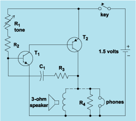
schematic diagram graphic arts
Schematic diagram. A presentation of the element-by-element relationship of all parts of a system.
A schematic diagram serves as a crucial tool in electronic design and engineering, representing the interconnections and relationships between various components within a system. It provides a...

How to Read a Schematic
Electronic circuits are presented in schematic form. A schematic is essentially a map that illustrates the path of current through various components. Each component is represented by a symbol, typically accompanied by a label or a value, or both. The...

Data-based Load Pull Amplifier
The AmpLoadPull project demonstrates the utilization of the AmpLoadPull and LoadPullSetup components in Advanced Design System (ADS). These components are part of the ADS behavioral model suite located within the System - Data Models palette. The schematic "circuit_level_amplifier_1_tone.dsn" represents a...
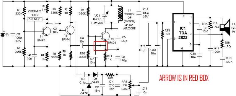
metal detector project circuit
A schematic diagram for a metal detector has been found. The project does not need to be original and can be sourced from the internet. There are several questions regarding this schematic. One query pertains to a small arrow connected...
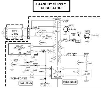
Need to have the circuit schematic for LG 29SA1RL model
The schematic is in PDF format and cannot be sent through this site. It is recommended to check a specific website that contains various schematics, including older posts that might have the schematic needed. A WS-55807 model is experiencing issues...

Remote-Controlled Telephone/Fax Machine Switch
This system uses a transmitter operating at approximately 100 kHz to control a remote receiver. A line splitter can connect the transmitter to the active telephone line. The transmitter is a CMOS oscillator equipped with output buffer stages to drive...
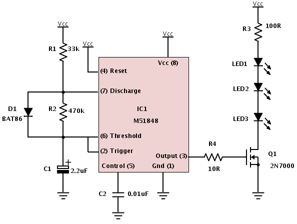
Building a device from a schematic
A common issue encountered is that individuals possess a schematic, also known as a circuit diagram, that they wish to construct. However, they discover that there are...
Building a circuit from a schematic requires a clear understanding of the components involved...

ELECTRONIC SCHEMATIC CIRCUIT DIAGRAMS
Electronic Schematic Circuit Diagrams Manual PDF Download.
The document provides a comprehensive manual that focuses on electronic schematic circuit diagrams. These diagrams are essential tools for understanding and designing electronic circuits, offering visual representations of circuit components and their interconnections. The...