


Diode Radio for Low Impedance Headphones
#diode radio
#low impedance headphones
#transformer
#RF receiver
#audio transformer
#headphone adapter
#mains adapter
#radio circuit
#signal transformation
#impedance matching

Description: The most commonly available headphones have an impedance of 2 × 32 Ω. This relatively low value makes them unsuitable for certain designs. However, with some clever modifications, these headphones can be adapted for such applications. To achieve this, a transformer from a mains adapter unit is required, specifically one that has a switchable output voltage (3/4.5/6/9/12 V) and does not include the rectifying diodes and capacitor. By utilizing the various taps of this transformer, it is possible to optimize the impedance match. In the case of the diode radio (any germanium diode is suitable for this design), achieving the correct impedance matching is crucial to prevent any loss of received signal energy. The antenna coil consists of a 10 mm diameter by 100 mm long ferrite rod, wound with 60 turns and featuring a tap point every 10 turns, making it suitable for medium wave reception. If a long external aerial is used, it should be connected to a lower tap point to minimize its damping effect on the circuit. Experimentation with all available tapping points is recommended to find the best reception. In this simple radio design, the external aerial significantly influences performance. Homeowners with metal guttering and rainwater pipes may utilize these as an aerial, provided they are not directly connected to the earth. Individuals living near a broadcast transmitter might connect a loudspeaker directly to the output, or if the volume is insufficient, they could try connecting an active speaker system from their PC.
The described circuit utilizes headphones with a low impedance of 64 Ω (2 × 32 Ω) which can be integrated into a radio design by employing a suitable transformer. The transformer serves to adjust the impedance, ensuring that the headphones can effectively work with the radio circuit without signal loss. The selection of a transformer with a switchable output voltage allows for flexibility in matching the impedance to the headphones and the overall circuit requirements.
The antenna coil is constructed on a ferrite rod, which enhances the inductance and, consequently, the efficiency of the radio receiver. The coil's configuration, with multiple tap points, facilitates fine-tuning of the circuit's performance. The tap points allow for adjustments in the impedance seen by the incoming signal, which is essential for optimizing reception quality. The use of a germanium diode in the circuit is a practical choice, as these diodes are known for their low forward voltage drop and suitability for RF applications.
For optimal performance, the connection of an external aerial is critical. The recommendation to use lower tap points when connecting an external aerial helps to mitigate the damping effects that can occur, thus improving the overall reception. The potential use of household metal structures, such as guttering and pipes, as an aerial is a creative solution to enhance signal reception without the need for additional components.
In scenarios where the radio is located near a broadcast transmitter, the output can be directly connected to a loudspeaker, which may provide adequate sound levels. If the audio output remains low, utilizing an active speaker system from a personal computer can significantly enhance the listening experience, making this design adaptable for various environments and user needs. Overall, the circuit design emphasizes the importance of impedance matching, proper component selection, and the strategic use of antennas to optimize radio reception.The most commonly available headphones have an impedance of 2 × 32 ?, this relatively low value makes them unsuitable for such a design. However, with a bit of crafty transformation these headphones can be used in just such a design. To adapt them, you will need a transformer taken from a mains adapter unit, the type that has a switchable output voltage (3/4.5/6/9/12 V) without the rectifying diodes and capacitor.
Using the different taps of this type of transformer it is possible to optimize the impedance match. For the diode radio (any germanium diode is suitable in this design) the key to success is correct impedance matching so that none of the received signal energy is lost.
The antenna coil on the 10 mm diameter by 100 mm long ferrite rod is made up of 60 turns with a tap point at every 10 turns; this is suitable for medium wave reception. If a long external aerial is used it should be connected to a lower tap point to reduce its damping effect on the circuit.
You can experiment with all the available tapping points to ?nd the best reception. With such a simple radio design, the external aerial will have a big in?uence on its performance. If your house has metal guttering and rain water pipes, it will be possible to use these as an aerial, as long as they are not directly connected to earth. Those who live in the vicinity of a broadcast transmitter may be able to connect a loudspeaker directly to the output or if the volume is too low, why not try connecting the active speaker system from your PC?
The described circuit utilizes headphones with a low impedance of 64 Ω (2 × 32 Ω) which can be integrated into a radio design by employing a suitable transformer. The transformer serves to adjust the impedance, ensuring that the headphones can effectively work with the radio circuit without signal loss. The selection of a transformer with a switchable output voltage allows for flexibility in matching the impedance to the headphones and the overall circuit requirements.
The antenna coil is constructed on a ferrite rod, which enhances the inductance and, consequently, the efficiency of the radio receiver. The coil's configuration, with multiple tap points, facilitates fine-tuning of the circuit's performance. The tap points allow for adjustments in the impedance seen by the incoming signal, which is essential for optimizing reception quality. The use of a germanium diode in the circuit is a practical choice, as these diodes are known for their low forward voltage drop and suitability for RF applications.
For optimal performance, the connection of an external aerial is critical. The recommendation to use lower tap points when connecting an external aerial helps to mitigate the damping effects that can occur, thus improving the overall reception. The potential use of household metal structures, such as guttering and pipes, as an aerial is a creative solution to enhance signal reception without the need for additional components.
In scenarios where the radio is located near a broadcast transmitter, the output can be directly connected to a loudspeaker, which may provide adequate sound levels. If the audio output remains low, utilizing an active speaker system from a personal computer can significantly enhance the listening experience, making this design adaptable for various environments and user needs. Overall, the circuit design emphasizes the importance of impedance matching, proper component selection, and the strategic use of antennas to optimize radio reception.The most commonly available headphones have an impedance of 2 × 32 ?, this relatively low value makes them unsuitable for such a design. However, with a bit of crafty transformation these headphones can be used in just such a design. To adapt them, you will need a transformer taken from a mains adapter unit, the type that has a switchable output voltage (3/4.5/6/9/12 V) without the rectifying diodes and capacitor.
Using the different taps of this type of transformer it is possible to optimize the impedance match. For the diode radio (any germanium diode is suitable in this design) the key to success is correct impedance matching so that none of the received signal energy is lost.
The antenna coil on the 10 mm diameter by 100 mm long ferrite rod is made up of 60 turns with a tap point at every 10 turns; this is suitable for medium wave reception. If a long external aerial is used it should be connected to a lower tap point to reduce its damping effect on the circuit.
You can experiment with all the available tapping points to ?nd the best reception. With such a simple radio design, the external aerial will have a big in?uence on its performance. If your house has metal guttering and rain water pipes, it will be possible to use these as an aerial, as long as they are not directly connected to earth. Those who live in the vicinity of a broadcast transmitter may be able to connect a loudspeaker directly to the output or if the volume is too low, why not try connecting the active speaker system from your PC?
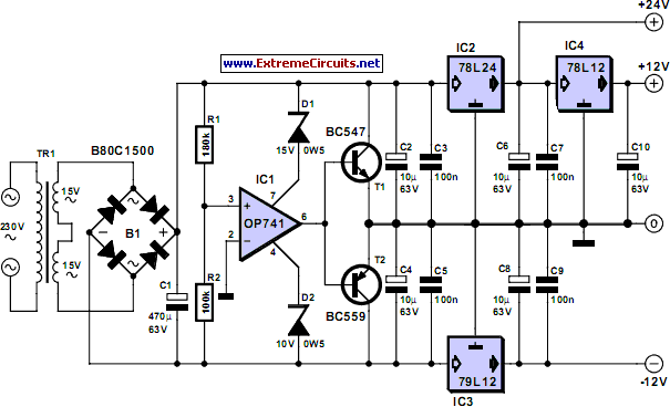
Triple Power Supply
Inexpensive miniature transformers typically provide one or two secondary voltages, which are sufficient for generating a set of positive and negative supply voltages, as required for operational amplifier circuits. However, if an additional voltage higher than either of the supply...
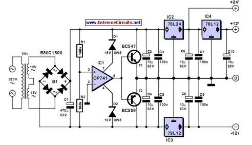
Triple Power Supply
Inexpensive miniature transformers typically offer one or two secondary voltages, which are adequate for producing a set of positive and negative supply voltages.
Miniature transformers are compact devices commonly utilized in various electronic applications, particularly in power supply circuits. These transformers...

The Simplest Car Battery Charger
This very simple circuit uses a transformer, two diodes, a capacitor, and an ammeter. To charge a battery, just connect the + and - terminals of the circuit to the corresponding terminals of the battery. When the battery is not...

Electric oven circuit
The circuit operates by activating switch SA1, which powers a 220V transformer that converts AC voltage to DC through a bridge rectifier, supplying power to the computer control panel. The temperature for cooking food is set on this control panel,...

PF Test Equipment
A transformer ratio-arm bridge circuit is utilized as depicted in the simplified diagram of Figure 1. The circuit comprises a standard reference capacitor (CS) and the insulation under test (CX). A distinctive feature of the circuit is a specialized multi-winding...
Diode Radio For Low Impedance Headphones
When examining construction notes for building vintage detector-type radios, the specified headphones typically have an impedance of 2 G—2000. In contrast, modern headphones generally have a lower impedance of 2 G—32, which makes them unsuitable for such designs. However, it...
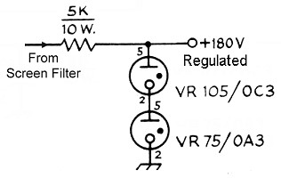
Power Supply Schematic
The power transformer features three secondary windings: 720V at 120mA center-tapped for the plate and screen supplies, 6.3V at 3.5A for the tube filament and bias power supply, and 5V at 3A (unused). Since the 5V secondary is not utilized,...

transformer Low voltage oscillator for joule thief
A transformer with two input leads and three output leads was used. An LED was connected to two of the output leads, and when a dead AA battery was connected to the input leads, the LED blinked for a brief...
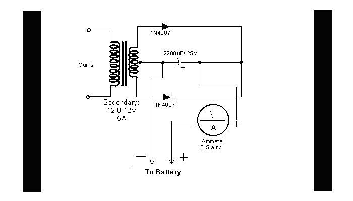
DIY Circuit Car Battery Charger
This simple circuit consists of a transformer, two diodes, a capacitor, and an ammeter. To charge a battery, connect the positive and negative terminals of the circuit to the corresponding terminals of the battery. When the battery is not charged,...