


Distributed parameter type microstrip circuit
#microstrip
#pre-amplifier
#IF amplifier
#distributed parameter
#RF circuit
#frequency band
#950-1470 MHz

Description: An IF pre-amplifier circuit is presented in a distributed-parameter microstrip configuration. It operates within the frequency range of 950 to 1,470 MHz. The output impedance is approximately 75 ohms. The power supply for the circuit is connected to the collector and base of the transistor VT2 through four short high-impedance microstrip lines. The base-emitter bias of the transistor consists of two components: one derived from the self-emitter voltage of the transistor and the other supplied by an external voltage source. A +15V power supply is utilized, with isolation provided by a high-impedance inductor in the microstrip line connected to the IF output.
The IF pre-amplifier circuit described utilizes a distributed-parameter microstrip design, which is advantageous for high-frequency applications due to its low loss and compact structure. The operating frequency range of 950 to 1,470 MHz is typical for intermediate frequency (IF) stages in communication systems, allowing for effective signal amplification while minimizing distortion.
The output impedance of 75 ohms is a standard value in RF applications, facilitating compatibility with other components in the signal chain, such as antennas and mixers. The design incorporates four short high-impedance microstrip lines to connect the power supply to the collector and base of the transistor VT2. This configuration minimizes signal reflection and ensures stable operation at high frequencies.
The base-emitter biasing arrangement is critical for the transistor's operation, ensuring that it remains in the active region for amplification. The self-emitter voltage provides a portion of the necessary bias, while the external voltage source contributes the additional required biasing voltage. This dual-source approach enhances the stability and performance of the amplifier.
The +15V power supply is essential for the proper functioning of the circuit, providing the necessary voltage for transistor operation. The high-impedance isolation inductor connected to the microstrip line serving the IF output prevents unwanted feedback and maintains signal integrity, ensuring that the amplified signal is delivered cleanly to subsequent stages in the signal processing chain.
Overall, the design of this IF pre-amplifier circuit reflects careful consideration of high-frequency performance, impedance matching, and biasing techniques, making it suitable for modern communication systems requiring reliable signal amplification.IF pre-amplifier circuit shown in distributed-parameter type microstrip circuit. It operates in the frequency band 950-1 470 MFk, output impedance of anti-75 Q, the collector and the base of VT2 vri pole power supply is provided through 4 short high impedance microstrip line: transistor base-emitter bias press consists of two parts: one is self-emitter voltage of the transistor, the other part is fed from an external voltage pole group. +15 V power supply is made by the high impedance IF output cable isolation inductor microstrip line fed.
The IF pre-amplifier circuit described utilizes a distributed-parameter microstrip design, which is advantageous for high-frequency applications due to its low loss and compact structure. The operating frequency range of 950 to 1,470 MHz is typical for intermediate frequency (IF) stages in communication systems, allowing for effective signal amplification while minimizing distortion.
The output impedance of 75 ohms is a standard value in RF applications, facilitating compatibility with other components in the signal chain, such as antennas and mixers. The design incorporates four short high-impedance microstrip lines to connect the power supply to the collector and base of the transistor VT2. This configuration minimizes signal reflection and ensures stable operation at high frequencies.
The base-emitter biasing arrangement is critical for the transistor's operation, ensuring that it remains in the active region for amplification. The self-emitter voltage provides a portion of the necessary bias, while the external voltage source contributes the additional required biasing voltage. This dual-source approach enhances the stability and performance of the amplifier.
The +15V power supply is essential for the proper functioning of the circuit, providing the necessary voltage for transistor operation. The high-impedance isolation inductor connected to the microstrip line serving the IF output prevents unwanted feedback and maintains signal integrity, ensuring that the amplified signal is delivered cleanly to subsequent stages in the signal processing chain.
Overall, the design of this IF pre-amplifier circuit reflects careful consideration of high-frequency performance, impedance matching, and biasing techniques, making it suitable for modern communication systems requiring reliable signal amplification.IF pre-amplifier circuit shown in distributed-parameter type microstrip circuit. It operates in the frequency band 950-1 470 MFk, output impedance of anti-75 Q, the collector and the base of VT2 vri pole power supply is provided through 4 short high impedance microstrip line: transistor base-emitter bias press consists of two parts: one is self-emitter voltage of the transistor, the other part is fed from an external voltage pole group. +15 V power supply is made by the high impedance IF output cable isolation inductor microstrip line fed.

The 2N5109 Amplifiers
This diagram originates from the Progressive Communications Receiver featured in most recent ARRL Handbooks. The amplifier is utilized wherever an intermediate frequency (IF) amplifier is necessary. W6BKY has published an article on Hamradio-online that details the construction of this circuit...

Circuit of RIIA phono pre-amplifier op-27
The circuit contributes 3.2 nV/√Hz of voltage noise and 0.45 pA/√Hz of current noise. To minimize noise from other sources, resistor R3 is configured to 100 ohms, resulting in an additional voltage noise of only 1.3 nV/√Hz. Resistors R1, R2,...

455 kHz IF WITH AF COMPRESSOR
A combination of an intermediate frequency (IF) amplifier, audio compressor, tunable audio filter, and audio output system operates from a single supply. The compressor and filter each utilize N5558V dual operational amplifiers or equivalent units. The tuning range of the...
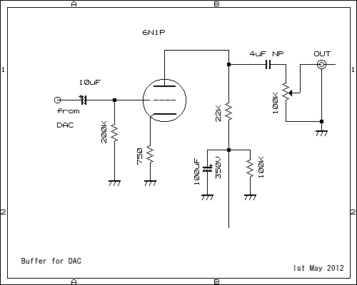
6DJ8 P-G Amp with DAC FN1242A Digital 2ch
This pre-amplifier can be driven directly from the DAC.
The described pre-amplifier is designed to interface directly with a Digital-to-Analog Converter (DAC). This direct connection allows for efficient signal amplification without the need for additional intermediary components, thereby simplifying the overall...

Video IF circuit TV Schematic Diagram
This section is designed to amplify the signal until it reaches the required level. The IF amplifier is equipped with an Automatic Gain Controller (AGC) that regulates the amplification to ensure a constant amplitude output for the video. The amplifier...

Simple Audio Pre-Amplifier
This straightforward circuit offers substantial amplification for weak audio signals, such as those from an electret microphone. It can be utilized in conjunction with an RF oscillator to create a highly sensitive RF transmitter. The audio microphone preamplifier circuit is...

Preamp Protection
While operating a two-meter single sideband (SSB) from the Benson area, it was determined that the local terrain and the limited height of a homemade six-element Yagi antenna necessitated the incorporation of a high-gain antenna pre-amplifier at its termination to...

TDA2549 TDA2549 I.F. Amplifier And Demodulator For Multistandard TV Receivers
The circuits utilize two FM Demodulator TDA2555 systems to execute the demodulation functions necessary in a dual sound carrier television system for demodulating the sound carriers. The distinction between the TDA2555 and TDA2557 lies in the number of stages in...

Racal RA17C18
The RA17C18 is a modified version of the RA17C12, featuring a delay-compensated IF amplifier and an additional IF output. It is designed for the North American market, utilizing BNC and SO239 connectors, with all fasteners having unified threads. The harmonic...