


Simple Audio Pre-Amplifier
#pre-amplifier
#LM358
#electret microphone
#audio gain
#signal amplification
#simple circuit
#inexpensive
#audio signal
#IC based
#sound sensitivity

Description: This straightforward circuit offers substantial amplification for weak audio signals, such as those from an electret microphone. It can be utilized in conjunction with an RF oscillator to create a highly sensitive RF transmitter. The audio microphone preamplifier circuit is based on a single LM358 integrated circuit. The design is simple, cost-effective, and easy to construct. The component parts list includes: R1, R3, R4 = 10K; R2 = 1K; R5 = 100K-1M potentiometer; C1 = 0.1uF; C2 = 4.7uF/16V; IC1 = LM358 dual op-amp, single supply; and Mic = Electret Microphone. The following diagram represents the schematic of a four-transistor FM transmitter circuit designed by Paul K. Sherby. The components list includes: R1, R2, R8 = 1K; R3 = 100K; R4 = 150K; R5, R7 = 10K; R6 = 220 ohm; R9 = 10 ohm; P1 = 5K trimpot; D1 = 1N4002; Q1, Q2 = 2N3904; Q3, Q4 = 7001, NTE123AP; C1. This FM transmitter circuit incorporates four radio frequency stages: a VHF oscillator designed around transistor BF494 (T1), a preamplifier utilizing transistor BF200 (T2), a driver stage employing transistor 2N2219 (T3), and a power amplifier based on transistor 2N3866 (T4). A condenser microphone is connected at the input. Additionally, a short-wave AM transmitter circuit design diagram is provided. This circuit is relatively simple and easy to construct, as it requires only a few electronic components. Its primary feature is the absence of an LC (inductor, capacitor) tuned circuit, operating at a fixed frequency of 12 MHz. This design represents a powerful three-stage, 9V FM transmitter (Tx) capable of achieving a range of up to 1 kilometer in open conditions. It utilizes an RF transistor in the output stage, along with two BC547 transistors for the first two stages. The transmission distance is critically dependent on the operating environment, whether indoors or outdoors.
This circuit operates effectively as a microphone preamplifier, enhancing weak audio signals for further processing. The LM358 IC serves as a dual operational amplifier, which is well-suited for audio applications due to its low noise and high gain characteristics. The use of an electret microphone as the input transducer allows for the capture of sound with minimal additional circuitry, making this setup particularly efficient for audio transmission tasks.
The FM transmitter design expands upon this concept by integrating multiple transistor stages to modulate and amplify the audio signal into a radio frequency signal. The inclusion of transistors such as the BF494 and BF200 allows for effective signal processing and amplification, while the 2N2219 and 2N3866 provide sufficient power for transmission. The circuit's design ensures that the audio input is faithfully reproduced at the output while maintaining a stable frequency, which is crucial for reliable communication.
The absence of an LC tuned circuit in the AM transmitter design simplifies the construction process and enhances reliability, as it eliminates the need for precise tuning components that can be sensitive to variations in temperature and component values. Operating at a fixed frequency of 12 MHz is advantageous for applications where frequency stability is paramount.
Overall, these circuits exemplify efficient designs for audio amplification and RF transmission, demonstrating the versatility and effectiveness of basic electronic components in achieving reliable communication systems.This easy circuit provides good gain to weak audio signals such as electret microphone. Use it in front of an RF oscillator to make an RF transmitter that`s very sensitive to sound. Here the simple audio mic pre amplifier circuit based on single IC LM358. The circuit is very simple, inexpensive and easy to built. Component Parts List: R1, R3, R4 = 10K R2 = 1K R5 = 100K-1M Potensiometer C1 = 0. 1uF C2 = 4. 7uF/16V IC1 = LM358 dual op-amp single supply Mic = Electret Microphone. The following diagram is the schematic diagram of 4 transistors FM transmitter circuit designed by Paul K. Sherby. Components List: R1, R2, R8 = 1K R3 = 100K R4 = 150K R5, R7 = 10K R6 = 220 ohm R9 = 10 ohm P1 = 5K trimpot D1 = 1N4002 Q1, Q2 = 2N3904 Q3, Q4 = 7001, NTE123AP C1.
This is the FM transmitter circuit which apply 4 radio frequency stages, that are a VHF oscillator designed around transistor BF494 (T1), a preamplifier designed around transistor BF200 (T2), a driver designed around transistor 2N2219 (T3) and also a power amplifier designed around transistor 2N3866 (T4). A condenser microphone is wired at the input of. Here the short wave AM Transmitter circuit design diagram. The circuit is quite simple and easy to build since it applies only a few electronic components. The primary feature of this transmitter is that it really is absolutely free from the LC (inductor, capacitor) tuned circuit and runs using a fixed frequency of 12 MHz.
This circuit is a powerful three stage, 9V FM transmitter (Tx) with a range of up to 1 kilometer in the open. It uses an RF transistor in its output stage and two BC547`s for the first two stages. Distance of trans-mission is critically dependent on the operating Conditions (in a building or out on.
This circuit operates effectively as a microphone preamplifier, enhancing weak audio signals for further processing. The LM358 IC serves as a dual operational amplifier, which is well-suited for audio applications due to its low noise and high gain characteristics. The use of an electret microphone as the input transducer allows for the capture of sound with minimal additional circuitry, making this setup particularly efficient for audio transmission tasks.
The FM transmitter design expands upon this concept by integrating multiple transistor stages to modulate and amplify the audio signal into a radio frequency signal. The inclusion of transistors such as the BF494 and BF200 allows for effective signal processing and amplification, while the 2N2219 and 2N3866 provide sufficient power for transmission. The circuit's design ensures that the audio input is faithfully reproduced at the output while maintaining a stable frequency, which is crucial for reliable communication.
The absence of an LC tuned circuit in the AM transmitter design simplifies the construction process and enhances reliability, as it eliminates the need for precise tuning components that can be sensitive to variations in temperature and component values. Operating at a fixed frequency of 12 MHz is advantageous for applications where frequency stability is paramount.
Overall, these circuits exemplify efficient designs for audio amplification and RF transmission, demonstrating the versatility and effectiveness of basic electronic components in achieving reliable communication systems.This easy circuit provides good gain to weak audio signals such as electret microphone. Use it in front of an RF oscillator to make an RF transmitter that`s very sensitive to sound. Here the simple audio mic pre amplifier circuit based on single IC LM358. The circuit is very simple, inexpensive and easy to built. Component Parts List: R1, R3, R4 = 10K R2 = 1K R5 = 100K-1M Potensiometer C1 = 0. 1uF C2 = 4. 7uF/16V IC1 = LM358 dual op-amp single supply Mic = Electret Microphone. The following diagram is the schematic diagram of 4 transistors FM transmitter circuit designed by Paul K. Sherby. Components List: R1, R2, R8 = 1K R3 = 100K R4 = 150K R5, R7 = 10K R6 = 220 ohm R9 = 10 ohm P1 = 5K trimpot D1 = 1N4002 Q1, Q2 = 2N3904 Q3, Q4 = 7001, NTE123AP C1.
This is the FM transmitter circuit which apply 4 radio frequency stages, that are a VHF oscillator designed around transistor BF494 (T1), a preamplifier designed around transistor BF200 (T2), a driver designed around transistor 2N2219 (T3) and also a power amplifier designed around transistor 2N3866 (T4). A condenser microphone is wired at the input of. Here the short wave AM Transmitter circuit design diagram. The circuit is quite simple and easy to build since it applies only a few electronic components. The primary feature of this transmitter is that it really is absolutely free from the LC (inductor, capacitor) tuned circuit and runs using a fixed frequency of 12 MHz.
This circuit is a powerful three stage, 9V FM transmitter (Tx) with a range of up to 1 kilometer in the open. It uses an RF transistor in its output stage and two BC547`s for the first two stages. Distance of trans-mission is critically dependent on the operating Conditions (in a building or out on.
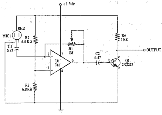
Electret Mic AmplifierCircuit Project
All resistors have a tolerance of 5 or 10 percent and are rated for 1/4 watt. All capacitors have a tolerance of 10 percent and are rated for 35 volts or higher. This circuit effectively amplifies the output of a...

Circuit of RIIA phono pre-amplifier op-27
The circuit contributes 3.2 nV/√Hz of voltage noise and 0.45 pA/√Hz of current noise. To minimize noise from other sources, resistor R3 is configured to 100 ohms, resulting in an additional voltage noise of only 1.3 nV/√Hz. Resistors R1, R2,...

electret microphone amplifier
Level refers to the relative strength of the signal and is measured in decibels. LINE level sources are much-amplified signals compared to MIC (microphone) level signals. Line level typically ranges from -10 to +4 dBm in strength, while MIC levels...
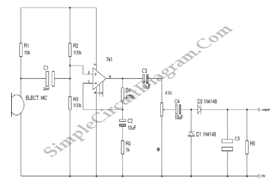
Audio Signal Strength Detector/Converter
Below is the schematic diagram of an audio input module. This module is capable of producing a DC output voltage that is proportional to the amplitude of the input signal.
The audio input module typically consists of several key components that...

Low energy consumption audio signal generator
On occasions when it is necessary to determine if an amplifier is functioning, the most effective tool is an acoustic signal source with a frequency around 1 kHz. The specifications can be considered flexible, as rapid tests typically do not...

Powering Electret Microphones
A condenser microphone (electret type with two terminals) is to be powered. A resistor of 1 kΩ and a capacitor of 10 µF have been connected to its positive terminal, while the other terminal is grounded.
To power an electret condenser...

lm358 alkaline battery charger circuit
There are two differing opinions regarding the charging of alkaline batteries. Some assert that charging is effective, while others caution against it due to the risk of explosion. It is acknowledged that rechargeable alkaline batteries can typically endure 30 to...

Tube Mic Pre-Amp
This is a simple audio microphone preamplifier circuit based on a single IC, the LM358. The circuit is straightforward, cost-effective, and easy to construct. The component parts list includes: R1, R3, R4 = 10K ohms, R2 = 1K ohm, R5...
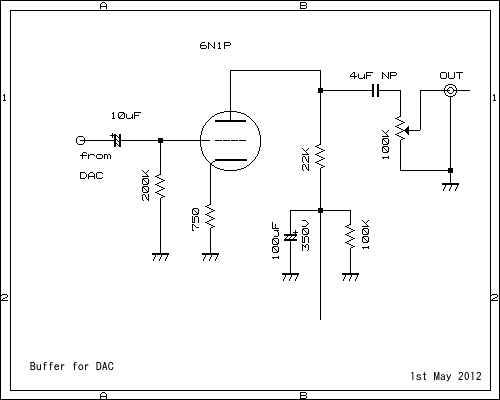
6DJ8 P-G Amp with DAC FN1242A Digital 2ch
This pre-amplifier can be driven directly from the DAC.
The described pre-amplifier is designed to interface directly with a Digital-to-Analog Converter (DAC). This direct connection allows for efficient signal amplification without the need for additional intermediary components, thereby simplifying the overall...