


LF Exciter using I2PHD/IK2CZL JASON

Description: The unit described here is simple to build, and can be quite small. The picture below shows the prototype, in a box 175mm wide, 210mm deep and 55mm high. The single circuit board is 140 x 90mm, so there's plenty of room inside for another board (a local control and LCD display board is planned). The design includes a linear amplifier, sine wave output and 60dB attenuator. The Exciter uses a Direct Digital Synthesizer, made using a high speed microcontroller, to accurately generate radio frequency sine waves from zero to about 400 kHz. All the work is done by the inexpensive microcontroller, so no expensive DDS chip is needed.
The described unit is a compact and efficient RF signal generator, utilizing a Direct Digital Synthesizer (DDS) architecture implemented with a high-speed microcontroller. This design choice allows for the generation of sine wave outputs with frequencies ranging from 0 Hz to approximately 400 kHz, making it suitable for various applications in radio frequency experimentation and signal processing.
The overall dimensions of the enclosure are 175 mm in width, 210 mm in depth, and 55 mm in height, which provides a compact form factor. The main circuit board measures 140 mm by 90 mm, allowing for additional circuitry, such as a local control interface and an LCD display board, to be integrated into the same housing. This modularity enhances the user experience by providing a visual feedback mechanism and control options directly on the device.
The linear amplifier within the design ensures that the generated sine waves are amplified to suitable levels for output, while the 60 dB attenuator allows for precise control over the output signal strength. This feature is particularly useful in applications where signal integrity and power levels are critical.
The microcontroller is the heart of the system, executing the necessary algorithms to produce the desired frequency outputs without the need for dedicated, high-cost DDS chips. This approach not only reduces the overall cost of the unit but also simplifies the design, making it more accessible for hobbyists and engineers alike. The use of a microcontroller also allows for potential firmware updates and modifications, enhancing the versatility of the unit over time.
In summary, this RF signal generator design combines a compact form factor with advanced functionality, leveraging a microcontroller-based DDS approach to produce high-quality sine wave outputs suitable for various electronic applications.The unit described here is simple to build, and can be quite small. The picture below shows the prototype, in a box 175mm wide, 210mm deep and 55mm high. The single circuit board is 140 x 90mm, so there's plenty of room inside for another board (a local control and LCD display board is planned). The design includes a linear amplifier, sine wave output and 60dB attenuator. The Exciter uses a Direct Digital Synthesizer, made using a high speed microcontroller, to accurately generate radio frequency sine waves from zero to about 400 kHz. All the work is done by the inexpensive microcontroller, so no expensive DDS chip is need
The described unit is a compact and efficient RF signal generator, utilizing a Direct Digital Synthesizer (DDS) architecture implemented with a high-speed microcontroller. This design choice allows for the generation of sine wave outputs with frequencies ranging from 0 Hz to approximately 400 kHz, making it suitable for various applications in radio frequency experimentation and signal processing.
The overall dimensions of the enclosure are 175 mm in width, 210 mm in depth, and 55 mm in height, which provides a compact form factor. The main circuit board measures 140 mm by 90 mm, allowing for additional circuitry, such as a local control interface and an LCD display board, to be integrated into the same housing. This modularity enhances the user experience by providing a visual feedback mechanism and control options directly on the device.
The linear amplifier within the design ensures that the generated sine waves are amplified to suitable levels for output, while the 60 dB attenuator allows for precise control over the output signal strength. This feature is particularly useful in applications where signal integrity and power levels are critical.
The microcontroller is the heart of the system, executing the necessary algorithms to produce the desired frequency outputs without the need for dedicated, high-cost DDS chips. This approach not only reduces the overall cost of the unit but also simplifies the design, making it more accessible for hobbyists and engineers alike. The use of a microcontroller also allows for potential firmware updates and modifications, enhancing the versatility of the unit over time.
In summary, this RF signal generator design combines a compact form factor with advanced functionality, leveraging a microcontroller-based DDS approach to produce high-quality sine wave outputs suitable for various electronic applications.The unit described here is simple to build, and can be quite small. The picture below shows the prototype, in a box 175mm wide, 210mm deep and 55mm high. The single circuit board is 140 x 90mm, so there's plenty of room inside for another board (a local control and LCD display board is planned). The design includes a linear amplifier, sine wave output and 60dB attenuator. The Exciter uses a Direct Digital Synthesizer, made using a high speed microcontroller, to accurately generate radio frequency sine waves from zero to about 400 kHz. All the work is done by the inexpensive microcontroller, so no expensive DDS chip is need

Attenuator schematic
Two low voltage, low power zeners are used to control electronically the level of an audio signal. The attenuation range is from 6 to 58dB for an input current from 0.042 to 77mA corresponding to a control voltage from 2.7...

tuned sine wave oscillator circuit
This design circuit is intended for sine wave oscillators, providing both sine and square wave outputs across a frequency range from below 20 Hz to above 20 KHz. The oscillation frequency can be easily adjusted by changing a single resistor....

Programmable-frequency-sine-wave-oscillator
A Wien-bridge oscillator can be made variable by utilizing two frequency-determining components that are adjusted simultaneously with high tracking accuracy. However, high-quality tracking potentiometers or variable capacitors are often costly and challenging to procure. To circumvent the need for such...
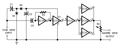
Sine to Square wave Converter
This circuit is intended to provide good square waves converting a sine wave picked up from an existing generator. Its main feature consists in the fact that no power source is needed: thus it can be simply connected between a...

Wien Bridge Sine Wave Oscillator
Achieving the appropriate amplifier loop gain is a significant challenge in generating a low distortion, constant amplitude sine wave. Nevertheless, this issue can be addressed with...
Amplifier loop gain is a critical parameter in the design of audio and signal processing...

Digital Sine Wave Generator Circuit
The digital sine wave generator (oscillator) circuit requires only a few components to produce signals with high amplitude constants and a wide range of variable frequencies. This circuit generates a sine wave signal, and by altering the values of resistors...

Modified Sine Wave Signal Generator
Pure sine wave inverters are optimal; however, they are costly to purchase or construct. Modified sine wave inverters can power certain equipment, while square wave inverters have more limitations.
Pure sine wave inverters are highly regarded for their ability to produce...

sine/cosine wave oscillator
When an alternating current signal is applied to a capacitor, the phase of the charging current and the voltage across the capacitor shifts by 90 degrees. Conversely, when an alternating current signal is applied to an inductor, the voltage change...

10W 10M Linear Amplifier Circuit
This linear amplifier provides a 10-W PEP output with a 1.25-W drive on the 10 m band. The transformers, T1, T2, and T3, consist of 10 turns of bifilar windings on an FT-50-43 toroidal core and are designed for broadband...