


Simple SWR Protection Circuit Easy to build
#SWR
#protection circuit
#directional coupler
#detector
#VHF
#RF bypass capacitors
#mica capacitors
#line coupler
#termination resistors

Description: This document outlines a simple SWR (Standing Wave Ratio) protection circuit that can be easily constructed. The directional coupler and detector components are sourced from an old VHF SWR meter. It is advisable to replace the existing RF bypass capacitors in the meter with higher-quality mica capacitors. Additionally, it is recommended to substitute the termination resistors in the line coupler with higher wattage alternatives while ensuring that the same resistance values are maintained to avoid inaccuracies in the SWR meter. Non-inductive resistors, such as carbon-film or metal-oxide types, should be used. The output of the circuit is connected to an LM3914 bargraph display, which lights up the LEDs to indicate the current SWR ratio. When the SWR ratio approaches 3, the circuit activates a relay that cuts off the RF input to the power amplifier. An alternative option includes using an LED indicator or sounding an alarm. Resources for further information include links to a 4W FM Transmitter Directional Coupler with RF Filter for 88-108 MHz and a 100W LCD PIC16F88 SWR Meter for VHF-UHF, as well as a program for designing analog meter scales.
The SWR protection circuit operates by monitoring the reflected power in a transmission line, which can indicate mismatches between the transmitter and the load (antenna). The directional coupler is the critical component that samples the forward and reflected power. It typically consists of a transformer or a resistive divider that separates these two signals. The detector then converts the RF signals into a DC voltage proportional to the SWR, which is subsequently processed by the LM3914 bargraph display.
The LM3914 is a versatile LED display driver that can drive up to 10 LEDs in a bar graph format, providing a visual representation of the SWR level. As the SWR value increases, more LEDs are illuminated, giving an immediate visual indication to the user. The relay acts as a protective mechanism, automatically disconnecting the RF input when the SWR exceeds a preset threshold, thus preventing potential damage to the power amplifier from excessive reflected power.
In constructing this circuit, attention must be paid to component ratings, particularly for the bypass capacitors and termination resistors, as these directly affect the performance and accuracy of the SWR measurement. Using high-quality components minimizes losses and ensures reliability. Furthermore, the choice of non-inductive resistors is crucial in maintaining the integrity of the RF signal, as inductive components can introduce unwanted phase shifts and distortions.
In summary, this SWR protection circuit is an essential tool for radio frequency applications, ensuring that the transmitter operates efficiently while safeguarding against potential damage from high SWR conditions. The integration of visual indicators and automatic shutoff features enhances usability and safety in RF systems.Here is a simple SWR protection circuit you can easily build. The directional coupler and detector components are from an old VHF SWR meter. You may want to replace the meter`s existing RF bypass Capacitors with higher quality (mica) ones. You may also want to replace the line coupler`s termination Resistors which higher wattage ones. Be sure to us e the exact same value, or the SWR meter will be inaccurate. Also, be sure to use non-inductive Resistors (carbon-film or metal-oxide will work). This then feeds to all LM3914 bargraph display to light the LEDs, indicating the current SWR ratio. SWR When the ratio reaches approximately 3, it will engage the relay, cutting off the RF input to the power amplifier. You could also just a LED light or sound an alarm if you want to. Visit this links for more, 4W FM Transmitter Directional Coupler with RF Filter for 88-108 MHz - 100w LCD PIC16F88 SWR Meter for VHF- UHF and click this link for building: The Windows ® program for drawing analog meter scales.
The SWR protection circuit operates by monitoring the reflected power in a transmission line, which can indicate mismatches between the transmitter and the load (antenna). The directional coupler is the critical component that samples the forward and reflected power. It typically consists of a transformer or a resistive divider that separates these two signals. The detector then converts the RF signals into a DC voltage proportional to the SWR, which is subsequently processed by the LM3914 bargraph display.
The LM3914 is a versatile LED display driver that can drive up to 10 LEDs in a bar graph format, providing a visual representation of the SWR level. As the SWR value increases, more LEDs are illuminated, giving an immediate visual indication to the user. The relay acts as a protective mechanism, automatically disconnecting the RF input when the SWR exceeds a preset threshold, thus preventing potential damage to the power amplifier from excessive reflected power.
In constructing this circuit, attention must be paid to component ratings, particularly for the bypass capacitors and termination resistors, as these directly affect the performance and accuracy of the SWR measurement. Using high-quality components minimizes losses and ensures reliability. Furthermore, the choice of non-inductive resistors is crucial in maintaining the integrity of the RF signal, as inductive components can introduce unwanted phase shifts and distortions.
In summary, this SWR protection circuit is an essential tool for radio frequency applications, ensuring that the transmitter operates efficiently while safeguarding against potential damage from high SWR conditions. The integration of visual indicators and automatic shutoff features enhances usability and safety in RF systems.Here is a simple SWR protection circuit you can easily build. The directional coupler and detector components are from an old VHF SWR meter. You may want to replace the meter`s existing RF bypass Capacitors with higher quality (mica) ones. You may also want to replace the line coupler`s termination Resistors which higher wattage ones. Be sure to us e the exact same value, or the SWR meter will be inaccurate. Also, be sure to use non-inductive Resistors (carbon-film or metal-oxide will work). This then feeds to all LM3914 bargraph display to light the LEDs, indicating the current SWR ratio. SWR When the ratio reaches approximately 3, it will engage the relay, cutting off the RF input to the power amplifier. You could also just a LED light or sound an alarm if you want to. Visit this links for more, 4W FM Transmitter Directional Coupler with RF Filter for 88-108 MHz - 100w LCD PIC16F88 SWR Meter for VHF- UHF and click this link for building: The Windows ® program for drawing analog meter scales.

2m VHF FM PMR transceiver to amateur radio converter
The PMR VHF transceiver Motorola Radius M110 (in further text referred as M110) was manufactured by Motorola GmbH therefore being an European radio. Since many professional radio service users has replaced this transceiver with newer gear, a considerable number of...
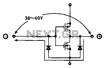
Various protection circuit structure and working principle diagram
Due to the varying conditions of different input signals, when an abnormal voltage is applied to the pin, protection circuits are designed to create a circuit path that secures the internal protection of large-scale integration (LSI) circuits. The structure and...

VHF Overtone Oscillator
VHF overtone crystals can be challenging to utilize due to the multiple frequencies at which the crystal can oscillate effectively. A typical 100 MHz, 5th-overtone crystal may oscillate at approximately 20 MHz, 60 MHz, 100 MHz, and even 140 MHz,...

TV Transmitter circuit diagram (VHF)
Many individuals inquire about TV transmitters. This document provides a useful circuit diagram that enables signal transmission over distances of 75 to 100 meters. The circuit diagram is not original; it was provided by a friend. Contributions of circuit diagrams...
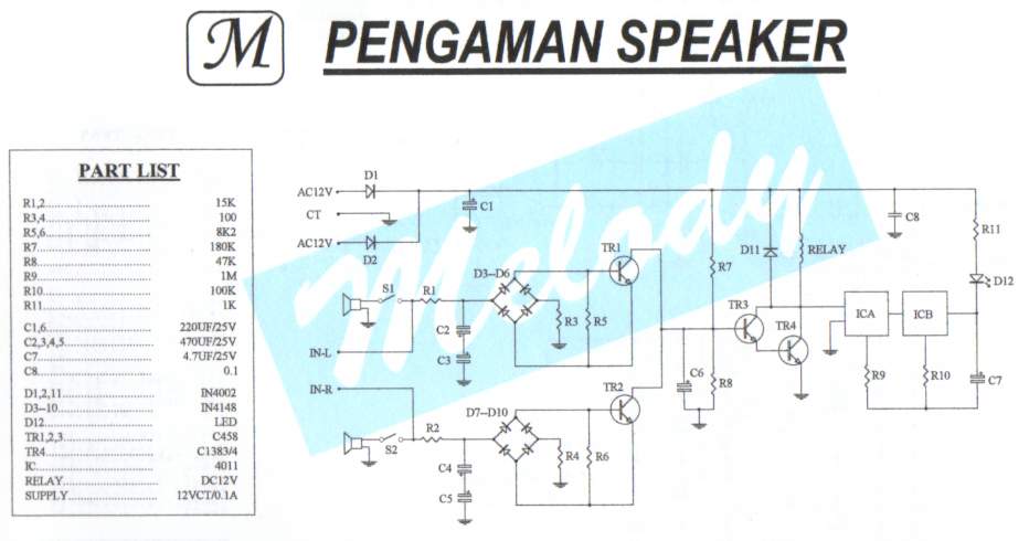
Safety / Protection Circuits
To prevent deep discharge that can damage or shorten the life of a rechargeable battery, it is essential to disconnect its load before the battery is completely discharged. The circuit protects against AC line disturbances by switching off the power...

GE/MACOM MASTR-III VHF Station
This article provides conversion instructions for radio model GE/MACOM MASTR-III Group 2 (150.8-174 MHz) Repeater or Base, Combination Number SXS, to enable it to operate effectively in the 144-148 MHz range. It is important to note that this document is...

Inexpensive Vhf/Uhf Diode Rf Switch
This circuit utilizes low-cost IN4148 diodes and demonstrates approximately 1.5 dB insertion loss across the frequency range of 10 to 1000 MHz with a few volts of negative bias. Under these conditions, diode D3 conducts while diodes D1 and D2...

VHF remote control
A few designs for remote control switches, using VG40T and VG40R remote control pair, are shown here. The miniature transmitter module shown in Fig. 1, which just measures 34 mm x 29 mm x 10 mm, can be used to...

MAX2606 VHF FM Transmitter
To test VHF receivers independently from local radio stations, a frequency-modulated oscillator is required, covering the range of 89.5 to 108 MHz. Building such an oscillator with discrete components is challenging. The MAX260x series from Maxim offers five integrated oscillator...